From RocketSlinger@SBCGlobal.net (email me there please)… This is a sub-site
to main site at www.rocketslinger.com …
This
web page last updated 18 July 2015
A Soft-Landing Method for Europa (or Other Icy
World) Using RPGs (Rocket-Propelled Grenades)
Abstract
This
sub-page to www.rocketslinger.com is
meant to describe a method of soft-landing on an “icy world” like Europa. Variations and embellishments are also
described, but the basics are as follows:
The lander spacecraft has a central vertical (in-line with its direction
of travel as it lands) structural, central spine that doubles up as a gun
barrel. A revolving (or other style of)
ammo-dispenser at the base of the gun (top of the lander) serves to feed
multiples (8, for example) of RPGs (Rocket-Propelled Grenades) cartridges to
the guns. The RPGs are rocket-propelled
only just enough to control their X and Y locations with respect to their
target locations; the “Z” axis is not covered, where the “Z” axis is parallel
to the downward direction of travel. X
and Y control on each RPG round means that (in conjunction with “robot-swarm”
intelligence on each round, informed by radio location transducers on each RPG
round) the small swarm of RPG rounds can embed themselves into the ice, in a
reasonable semblance of a circle. By
forgoing the “Z” axis of directional control, the RPG rounds are entirely
“Z”-propelled by the explosions in the gun, delivering maximum “kick-back” or
retro-grade propulsive impact to the lander.
Mid-flight-deployed fins snap out on the RPG rounds, so as to prevent
them from penetrating into the ice, too deeply.
The RPG rounds embed themselves into the ice in a round
pattern, at near-optimal depth. Their
on-board intelligence allows them to await an explosion command from the
lander. The lander approaches a landing
spot in the middle of the round pattern of charges. At the appropriate time, the charges are set
off. The shock waves (and dislodged ice,
some of which will turn into liquid water and steam) will converge and collide
in the center of the circle of explosions, creating an upward geyser. The lander’s bottom is covered by an impact-resistance,
energy-absorbing shield. The shield does
three things: It protects the lander,
and (in conjunction with the impact forces of the central geyser) stretches out
in time, the deceleration of the lander (reduces peak “G” forces), and softens
out the final landing on the hard icy surface, killing whatever lander-speed is
left after the backward “kicks” of the gun, and the geyser impacts.
Alternatives for materials and construction of the gun and
the energy-absorptive shield, as well as overall design alternatives, are
described here.
Also note that, although this design is intended for
landing on ice (which will at least partially liquefy and gasify, making for a
softer landing), it might also be able to be adapted to landing on a rocky world,
like the Earth’s moon, or Mars. Rocks,
sand, and gravel impacting onto the landing shield will be more difficult to
deal with, though, than chunks or particles of solid, liquid, and gas phases of
water.
The Gun
The
gun barrel needs to be optimized for minimal weight, with costs being far less
important (since every pound of mass thrown this far into space, comes at very
high costs). The gun barrel needs to
withstand only a minimal number of rounds (explosions) as well. Many alternatives are possible; Here is one proposal.
The innermost layer of the gun barrel (the layer that
touches the RPG rounds and the exploding gasses) might, for minimal mass, be
constructed of a bare-minimal-tolerable, plus safety margin, thickness of
“glassy metals”, AKA “amorphous metals”.
Such glassy metals are well known and documented by now, so no links are
provided here. Similar high-tech
materials could involve laser-sintered quasi-crystals;
see http://www.sciencedaily.com/releases/2014/10/141030100331.htm
“3-D printing
incorporates quasicrystals for stronger manufacturing
products”.
Alternatively, the designers could go with
more prosaic materials, such as a thin layer of tool steel or stainless
steel. Think of this layer as the hard,
thin layer on teeth… The
enamel layer.
The next layer, moving outward, may or may not be
needed. It may be needed to provide
thermal insulation from the innermost to the outermost layers of the gun barrel
(to protect the outermost layer from high temperatures), and/or, it may be
needed to for additional mechanical strength (explosive-forces tolerance),
and/or, to accommodate forces generated by different materials expanding and
compressing at different rates, due to temperature changes. It should be less dense than “glassy metals”,
and need not be as hard as glassy metals.
In the teeth analogy, it is “dentin” compared to the “enamel” of glassy
metals. It could be arranged in
concentric layers, abutting one another (with air gaps, or more properly,
vacuum gaps, between segments), to provide for differential thermal expansion
and contraction. (Most likely high-tech)
suitable materials for this layer should be high-temperature tolerant, but
lightweight. Here are examples:
http://www.sciencedaily.com/releases/2014/06/140610121803.htm
“High strength
cellular aluminium foam for the automotive industry”,
and
http://www.sciencedaily.com/releases/2015/05/150512164522.htm
“A metal composite that will (literally) float your boat”.
The final, outermost layer of the gun
barrel might best be constructed out of lightweight, highly stretch-resistant
material. This material, optimally, may
not need to be high-temperature tolerant.
There are already at least two well-established applications for woven
carbon fibers to be used in similar applications. For example, for wrapping concrete structural
cylinders, see http://www.concreteconstruction.net/concrete-strength/wrapping-it-up.aspx
“Wrapping it Up (return) Strengthening concrete members with carbon
fiber fabric and epoxy composites”, and for commercially available gun barrels,
see http://www.brownells.com/items/carbon-fiber-gun-barrel.aspx
(for just one randomly grabbed sample).
If the designers want to spend the extra time, trouble,
and money to go higher-tech for even better numbers for strength and light
weight (mass) for this outermost layer, see http://www.sciencedaily.com/releases/2015/05/150515001353.htm
“First large-scale graphene
fabrication”… Graphene
sheets could be rolled up into cord-like or string-like shapes, which could
then, in turn, be woven together.
A cross-section of the gun barrel,
then, would look like the below illustration:
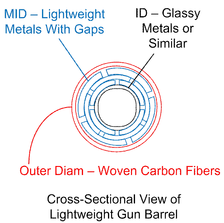
Figure
#1
The Shield / Shock Absorber
The
shield / shock absorber will shield the bottom of the lander from the impact
forces of chunks of ice that impact the lander, from the bottom of the lander,
as the lander settles down upon the “geyser” of materials that are thrown
upwards as the circle of slightly-buried (circle-arranged) RPGs explode. If any reader is confused, or needs more
details, more drawings are easy enough to generate… Explosions patterns, centrally converging
shock waves and ice-water-steam being thrown towards the central “geyser” and
converging, then being deflected upwards…
All that is easy enough to illustrate…
Just email me at
RocketSlinger@SBCGlobal.net
, please… Another way to summarize the
scheme is, we are “cheating” on carrying reaction mass, here, if you will. To go only slightly off-color, here,
propulsion often means “throwing mass out of your ass”, to get a Newtonian
“action proportionate to reaction”… Why
not borrow the mass of your target, to react against? That’s what we’re doing here…
Here is a parenthetical note for you fans of the history of
space travel ideas: Do you doubt my
variation upon “mass out your ass”, whereby we make a slight variation, and
don’t actually throw “mass out your ass”, and instead, use the impact velocity
of mass being thrown into your ass, if you will? Well, how about “going nuclear with the
idea”, and going to “Project Orion”, where we absorb the energy (and mass) of
nuclear explosions being thrown into shock absorbers on our aft end? See https://en.wikipedia.org/wiki/Project_Orion_(nuclear_propulsion)
. This proposed-but-never-built idea is
VERY similar to the exploding-grenades idea proposed here, in that
explosions-driven matter and energy is directed at shock absorbers on the aft
end of a spacecraft.
Anyway, one possible approach is to build a “layer cake”
shield out of semi-rigid plates (made out of deformable, impact-absorbing
metals, for example) and energy-absorbing “crunch zones” of lightweight,
solidified foams. An everyday example of
energy-absorptive, crunchable foam, that most readers will be familiar with, is
insulating spray foam. See
https://en.wikipedia.org/wiki/Spray_foams_(insulation) for the basics. Also
see http://www.sprayfoamkit.com/blog/2011/10/temperature-and-spray-foam-insulation/
, where we learn that “SFI has
the best adhesion and most ideal curing process when it is applied in 60-80F
degrees (15-26C).”
At
launch-from-Earth time, not only do we want to reduce the weight of the
launched assembly; we also want to reduce the volume. Extra volume means extra air resistance
during the launch process, at lower altitudes.
So we will want to wait till we are in low Earth orbit, or higher,
before filling “crunch-zone voids” in our shields. There may be trade-offs involved here… For higher cure temperatures, we will want
fill the shield-voids with spray foam, ASAP after leaving Earth’s atmosphere
(where we are still closest to the sun’s heat).
The foam, however, may possibly degrade over time, if it is cured a long
time before it is crunched (before impact on Europa). If needed, “resistance wires”
(steel-nickel-chromium heating wires) could be added. The lander would pre-heat one segment (and
spray can) at a time, before filling each segment (void) with spray foam to be
cured during travel.
A large void
entirely filled with foam will be heavier and stiffer than needed. So what is envisioned here is a centrally located, strangely shaped bag (made of canvas, plastic film,
or graphene, say) that will be collapsed (empty)
during initial launch. It is like a
round pancake, with a hole in the middle, to accommodate the gun barrel and
RPGs travel path (like a flattened doughnut, including a hole in the
middle). Protruding from the top and
bottom of the flattened doughnut, there are “fingers” added, for the express
purpose of absorbing impact energy. At
launch time, these strange-shaped, deflated (empty) bags are layer-caked with
alternating energy-absorbing but rigid metal plates (also in the shape of
flattened doughnuts). The over-all
(simplified) design, prior to inflation of the shock-absorbing bags, might look
something like this cross-sectional view:
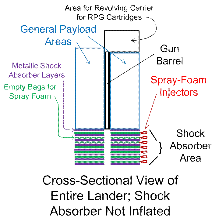
Figure
#2
Before
we forget, now, let’s mention what the metallic layers of the “layer cake” of
the shock absorber might be made of: A good candidate is as follows:
http://www.sciencedaily.com/releases/2013/12/131203091453.htm
“Citrus fruit
inspires a new energy-absorbing metal structure”.
The next drawing will elaborate on
what shapes of the bags should be, when filled with the impact-energy-absorbing,
sprayed foam, so as to minimize weight while also maximizing “crunch space”
(which translates to minimized max-gee-impact forces, by spreading deceleration
over time). The same color scheme is
retained from the previous drawing. Once
again, the “to-be-crunched” layer of spray foam takes the shape of the
containing bag, which is a flattened doughnut (torus) shape, with “fingers”
protruding from top and bottom. The
“fingers” could be straight and simple…
But then they would buckle and break once, which is not optimal. “Optimal” is up for discussion, obviously,
but this writer believes an optimal shape would be a
helix or screw-shape… It bends all along
its body, then breaks, with space left between these helical “finger-bags” for
broken pieces to fit into… Stretching
out the “crunch time” and minimizing the maximum “peak G forces” upon
impact. So… On, to the drawing:
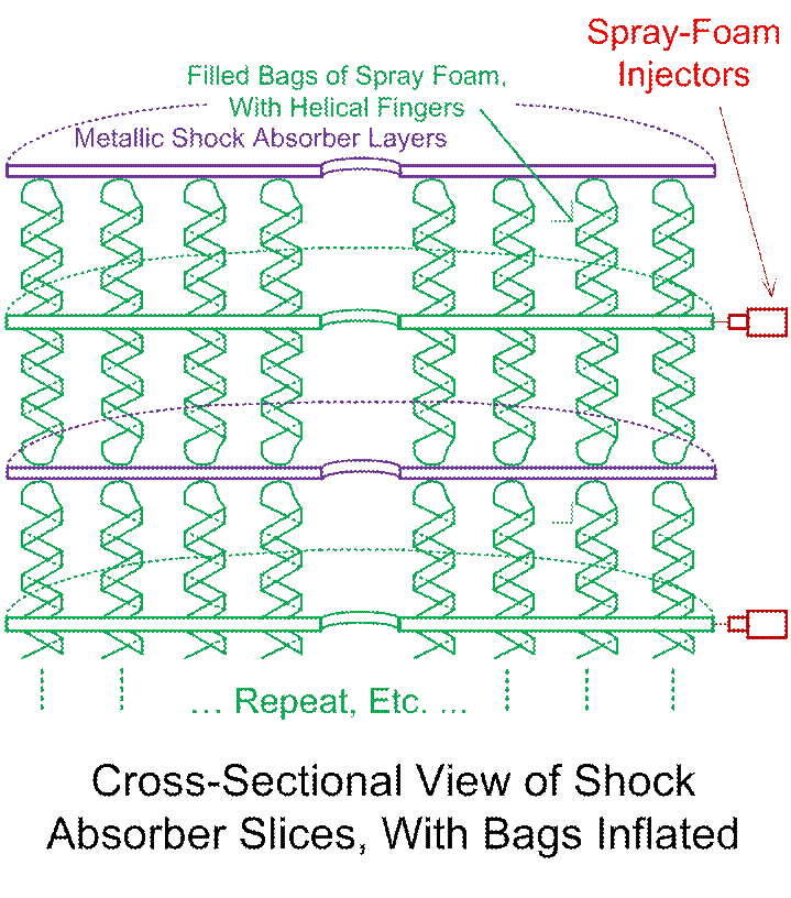
Figure
#3
The
above only shows the helical “fingers” (growing out of the top and the bottom
of the doughnut-shaped bag) in a single line, to reduce visual clutter. In reality, they should be spaced, at
moderate density, across the entire surfaces of the doughnut. Also to reduce visual clutter, control (and
probably power to the “resistance wires” as well) wires to the inflating spray
cans are not shown. “Control wires”
would, for example, open solenoids to spray-foam-fill the bags
after the spacecraft is out of the Earth’s atmosphere.
Now,
what happens if the (inflated, deployed) shield / shock absorber needs to be so
tall, that a “topple hazard” sets in, whereby the entire lander could topple
over to the side, and be damaged? To
cover this, the designer might consider sacrificing a bit of “payload area”, so
as to array a bottom circumference of outward angled helical foam bags… Perhaps a thick array of
various lengths, all around this bottom, outer perimeter. Here is another top-level cross-sectional
drawing, which will hopefully be enough to illustrate the general idea:
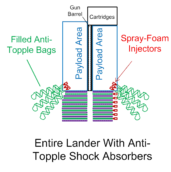
Figure
#4
The
above drawing, for simplicity, shows the anti-topple bags as inflated, and the main
stack as not being inflated; hopefully, this is enough to be generally
illustrative. If not, once again, please
email me at RocketSlinger@SBCGlobal.net
. Also note: A probably-more-sensible arrangement, better
than what is shown, would be for the entire bottom of the payload area to be
surrounded by a large inner-tube-like toroid shape (filled with solid foam),
and for the anti-topple “fingers” to protrude out from there. This would help to prevent one finger from
becoming entangled with another, as they all inflate, and would mean that (as
the entire assembly came into danger of toppling severely), the solid-foam
toroid shape would provide much more “crunch resistance” than the fingers
alone. After all these anti-topple
provisions are made, the lander is still not guaranteed to make its final
landing, anywhere near totally flatly.
Other provisions will have to be made to accommodate this. Yet another idea is to cover even more of the
surface of the “payload area” with spray-foam-filled bags… Such bags being detachable,
post-landing, if needed.
This
concludes the most-essential, core ideas to be presented here. The remaining items below are non-essential
alternative ideas, variations, and explanations.
Minor Details & Options FYI…
Some
of the below will be rather obvious to some of my readers, if I have any
readers! If you are a real rocket
scientist, some of it will be totally obvious…
If not, some ideas may not be so obvious. Are you, Dear Reader, just
an amateur dabbler like me, wanting to kick the ideas around? In either case, do you need or want
more? Email me please… RocketSlinger@SBCGlobal.net
… More illustrations are easy enough to provide…
Europa,
of course, orbits Jupiter. As the
assembly of main spacecraft, plus lander, enters the Jupiter (“Jovian”) system,
a fairly large amount of (expensive) reaction mass will have to be spent to put
the assembly into Jupiter orbit. We have
to kill our “coming here from Earth” velocity, that is. Then, some more will have to be spent to put
the assembly into Europa orbit, as I understand. One variable that I do NOT understand, is how
high, or how low, of an orbit, around Europa, is desired, for this assembly of
the main orbiter, plus lander? I could
help “crunch the numbers” here if desired, but would need an answer to that
question, for starters…
Anyway,
it is assumed here that the assembly would be placed into Europa orbit, for
quite a few orbits, while data is collected and analyzed. Only after careful analysis, THEN the mission
management would select an optimal target for the lander. That means that the combination of reaction
mass going out the lander’s gun, and the “crunchable” shield / cushion, would
be good ONLY for killing accumulated descent velocity… That is, the assembly first orbits
Europa. Lander target is selected, and
lander detaches. Lander can NOT use the
“gun”, now, for killing Europa-orbital velocity, except if additional ammo
“rounds” are reserved for this purpose, and for this purpose alone… Having these “rounds” serve a double purpose,
as being also the RPG rounds to be pattern-buried in the ice, to create our
landing-softening central “geyser”, is simply not practical. Orbital-velocity-killing rounds must be shot
in a direction radically incompatible with what would be needed for RPG rounds
that double up to kill descent velocity.
Need details? Email me…
So
anyway, we kill the lander’s Europa-orbiting speed via emissions of compressed
gasses, or conventional rockets, or gun rounds carried for that express purpose, and for that purpose alone. Carrying the extra gun rounds to do this, is actually fairly sensible… If we decide to go with the RPGs scheme for
starters, then we need to carry the gun barrel anyway, so why not? Gun technology is VERY reliable, and the
specific impulse (propulsion proportional to reaction mass carried,
or, speed of the ejected mass) is pretty respectable… Certainly better than that
of compressed gasses, for example.
This (extra gun rounds carried for orbit-killing) is a viable
alternative, then. So kill your orbital
velocity first, then Europa’s gravity will slowly
speed you up, bringing you in for a vertical collision into the surface (ice). This vertical “fall speed”, and this, alone,
is what you can help “kill”, with the RPG rounds fired straight downwards.
All
the above assumes, though, that we want to assume Europa orbit first, before
selecting a landing target. If this assumption is discarded… If we can pre-select our
landing target before entering Europa orbit… Or even, at a logical extreme, before
entering Jupiter orbit… Then the lander
could detach from the orbiter, earlier in time, and yet more total reaction
mass could be saved… The lander could
approach the surface of Europa with even greater speed, above and beyond just
that which is created by the gravitational attraction of Europa. I am no rocket scientist, but this sounds
risky to me! In the interests of being
complete, though, this possibility…
Having the RPGs-powered landing scheme cover more than just the
gravitationally-induced “fall” of the lander, and the price to be paid for
it… Is covered, here.
If considerations of reliability and
specific impulse (and others?) permit, it might even be desired to use the
lander’s gun to kill velocity of the entire assembly of orbiter plus lander, as
the assembly enters Jupiter orbit, and/or, as the assembly enters Europa
orbit. I cannot think of why this
couldn’t be done. This option would
preserve the probably-much-treasured option of studying Europa’s surface, up
close and (almost) in person, before selecting a landing site, while also using
the gun for all that it is good for. If
one objection to the gun is lack of precise control, then a solution might
be: Use the gun to kill 95% +/- 2% or so
of speed needing killed, and some other method, for the final fine-tuning.
Major Option… Use of “Shaped Charges”
Dear
Reader… We are “brainstorming” here,
including all ideas. Join me at will… RocketSlinger@SBCGlobal.net ,
once again… I don’t honestly know which
ideas are most practical. I personally
consider only ONE remaining idea to be very practical (but list more “for grins”
further below). The one (optional) idea
that I consider to be most practical is as follows: So far, we have discussed a circular pattern
of RPGs (Rocket Propelled Grenades) that bury themselves into the surface ice,
without mentioning an idea that would require a bit more complexity in the
control circuitry onboard these RPG rounds:
This is OPTIONAL, now, but… To
increase the efficiency with which the exploding RPG rounds “blast” ice towards
the central “geyser” (created when all the icy streams collide in the center),
we could use “shaped charges”. This
would require the RPG rounds to land in a manner in which their ORIENTATION (as
well as their location) is controlled.
“Shaped
charges” simply means that the explosive is “shaped” such that one part of it
explodes, then another, then another, and so on. The timing is usually a matter of
milliseconds (thousandths of a second) from one area of the explosive to
another, as I understand it… Also,
air-gaps or voids or fillers or metal plates may be involved. See https://en.wikipedia.org/wiki/Shaped_charge
for details. I am no expert here at all,
and am lazy; have not studied up on it!
Suffice it to say, I think that if the orientation of each RPG round was
controlled, the explosions could be “shaped” to throw more ice in the desired
direction, and less in the un-desired directions. You experts out there, please chime it…
Minor Option… Last “Cartridge” is a Sample
Collector
Now we
will delve into what I consider to be less practical “wild and crazy” ideas,
but here they are… Some will not be
compatible with other ideas.
The last “cartridge” at the
base of the gun barrel could serve as a sample collector… It could be an empty cartridge. The down-ward-pointing “business end” of the
gun barrel could be funnel-shaped (blunderbuss style), so as to collect ice,
water, and steam, as the lander travels through the central “geyser”, and a
solenoid could slam shut at the entry to the empty cartridge, at the
near-precise moment of final landing, to capture and contain the sample that
was taken. The sample would be
contaminated by the remnants of the explosive charges, is one disadvantage. The near-certain need for a funnel is
another… The funnel would need to go,
where the shield / shock absorber needs to go.
Minor Option… Scrounging for Reaction Mass
After
each individual round is fired, the casing that held the explosives to propel
the bullet, or RPG, is wasted mass. At a
bare minimum, the casing should be as lightweight as is possible, and the empty
casing should be ejected from the spacecraft, after the round is fired. Carrying an empty case would mean just that
much more useless mass that needs to be decelerated, that is. These 2 options mentioned so far, should be
sufficient. At some extreme of the
imagination, though… This sounds too
“Rube Goldbergish” to me… We could add mechanisms to grind up the
remnants of the empty casings, and / or eject them from the spacecraft, with
some significant velocity. Cramming the
ground-up remnants into the gun barrel, before the next round is fired, is one
option.
After
the gun is fired the last time, the cartridges dispenser, and/or the gun barrel
itself (in fragments if possible) could be expelled “at significant speed”
also. Seeing as to how we want to
accumulate as much “fall speed” as possible, though, as we descend to the
surface, before killing said “fall speed”, there will not be much time
available for such schemes to work. In
the name of completeness, though, the idea is hereby mentioned…
Minor Option… Gun Barrel Doubles up as “Pogo
Stick”
Instead
of using a spray-foam-based (or other) shield and shock absorber, the gun could
be mounted on large (mechanical or other, most likely mechanical) springs. As the rounds are fired, the entire gun
recoils and recovers on these springs…
This reduces the sharp peak G forces (on the payload) as each round is
fired. If the payload is mounted at the
base of the gun, the gun barrel is long, and the springs are strong enough, we
could get some “pogo stick” action as the lander hits, bounces, hits again,
bounces, etc., till the bouncing is done (energy dissipates as heating and
other inefficiencies in the springs, for example).
This
would obviously require active “balancing” in the payload, to keep it vertical,
as the bounces subside. It would also
require the lander to be tolerant of “falling on its side” after the last
bounce of the pogo stick. The active
balancing could be done via: ‘A) Rockets, the release of compressed gasses, or
other conventional means, or ‘B) the spinning of internal, fairly large
gyroscopes (wheels), which, of course, requires additional mass, which is of no
other use… Unless their spin energy is
later tapped as an energy supply? Or
they are made of, or contain, chemicals that can be dissolved or otherwise
processed to be combined in, say, a fuel cell, for energy supplies? Just blabbering at the keyboard here…
Europa’s surface seems likely to be made of
fairly pure ice, but also some ice that is highly contaminated with salt… See http://www.nasa.gov/topics/solarsystem/features/europa20130305.html
, for example. I am no expert here, but
it seems to me that more-pure ice is going to be hard, and salt-contaminated
ice will be softer. If the lander is
going to have little mobility (not be a rover), then the limited mobility
afforded by the “pogo-sticking” timeframe (if intelligently guided on-site and
in real time) may be of value. The
initial impact of the lander could be on more-solid ice, with subsequent
“bounces” directed towards ever-softer, ever-saltier areas. Otherwise, it may be possible that the
initial (higher-speed) landing would be in a too-salty, too-soft area, and the
whole lander could be buried. So the
pogo-stick approach may actually be a reasonably sharp idea.
Various
other variations and combinations of the above-described ideas are
possible. Among them might be,
discarding the idea of using grenades (with explosives inside the projectiles)
and going purely with kinetic energy only.
It is perhaps possible that such purely-kinetic rounds could be fired
accurately enough, with differential speeds on all of them according to how
soon or how late they are fired (as controlled by how much or how little of an
explosive charge is used for sending off each round), that such purely-kinetic
rounds could still provide a circular pattern of near-simultaneous impacts, to
create a landing-softening central “geyser”.
I suspect that this is impractical, but I am no expert. Perhaps one way to make the idea be more
practical, would be to have the gun-and-ammo part of the lander separate from
the payload part of the lander, well ahead of time, during the descent of the
two separated parts, so that the timing relationship of the payload v/s
“geyser”-creating bullet impacts can be adjusted appropriately. This idea, though, obviously subtracts out,
the use of the retro-“kick” of the gun, to slow down the payload part (unless
we use a long, rope-like tether, so that the two parts are not totally
separated?). This brings us to the final
set of ideas to be presented here (for now).
Using Copper Bullets and Spectroscopy
Instead
of using grenades, then, let us consider using copper bullets, and
spectroscopy, so that the orbiter can observe multiple copper-bullet impacts on
the surface of Europa. Copper is used,
where copper is not expected to occur in significant amounts in Europa’s ice,
and so that copper’s signature in the spectroscopic readings can be discounted
(ignored). This method has already been
used with success… See https://en.wikipedia.org/wiki/Deep_Impact_(spacecraft)
, for example. The Japanese space agency
has a somewhat similar mission in progress; see http://www.newstatesman.com/future-proof/2014/09/japan-readies-space-probe-mission-chase-asteroid-and-shoot-it-cannon
.
What
this might look like, for a Europa mission, might be for the lander to detach,
and make a small retro-blast (via gun or more conventional propulsion) to lower
its orbit (and tighten it, or lessen the time for one orbit), so that its orbit
is lower and faster than that of the main orbiter. One or more orbits pass by, till the timing
and positioning is just right, so that the lander can begin its “strafing run”
on Europa, with the main orbiter optimally positioned above the string of
impacts created by the copper bullets.
The orbiter uses spectroscopy and photography to gather as much data as
is possible, about the composition of the icy and salty-icy surfaces on Europa,
as is released by the bullet impacts.
Good precision targeting of the rounds may or may not be practical, but
hitting a variety of different target-types should be easy enough, even with a
bit of randomness being present.
The
orientation of the lander could be controlled by large internal gyroscopes, and
/ or conventional orientation-controlling rockets or compressed-gas ejectors
(thrusters). The very first rounds are
shot at or above the approaching horizon or Europa, to optimally kill orbital
velocity. These first rounds will, then,
obviously not be useful for gathering data about their impacts. But the lander will,
over time, fire more rounds… As it gradually transitions from an orbit to an
almost-straight-down drop. That
is, with proper control of the lander’s, and its gun’s, orientation, the aft
end of the lander (and “business end” of the gun, one and the same) will slowly
transition from being aimed at the approaching horizon, to being aimed
nearly-straight-down at Europa’s surface.
This will create a line of many bullet impacts that can be
analyzed. The very last round should be
fired at a point in time that is fairly close to the final soft landing, so
that minimal “fall speed” can accumulate between the last velocity-killing
blast of the gun, and the final landing.
The
payload part of the lander should detach from the gun after the last round is
fired, and the majority of the “falling speed” has been killed by the gun’s
retro-kicks. The payload part of the
lander can then make the final landing via more conventional propulsion
(rockets or compressed gasses).
In
this scenario, the ideas about a “central geyser” and a crunch-able landing
shield / cushion are almost definitely best discarded. The base of the gun (ammo dispenser) might
best be coupled to the lander, with provisions (electromechanical devices or
small explosive bolts) for the two to be separated. The final lander, of course, is positioned
above the gun… The gunpoint is always
positioned at the leading edge of travel, for the entire approach to
landing. The two separate, and the final
lander part “flies away” just barely far enough from the gun, to guard against
any kind of collision upon final landing.
The lander could then have “legs” that are cushioned by mechanical
springs, gas pistons, or other methods of giving the payload an optimally soft
landing. The final lander might bear a
slight resemblance to the Apollo moon landers, then.
This
last, above-described option, unlike earlier options, would not easily allow
the lander to “steal mass” from the ice at Europa’s surface, to soften the
landing. This is a relative
disadvantage. However, the provision
for purely-kinetic bullet impacts to provide data to the orbiter,
is a definite advantage. More
illustrations can be provided upon request…
This concludes my ideas as of this time. Please send feedback, suggestions, additions,
etc. …
Stay
tuned… Talk to me! RocketSlinger@SBCGlobal.net
Back
to main site at www.rocketslinger.com