From RocketSlinger@SBCGlobal.net (email me there please)… This is a sub-site
to main site at www.rocketslinger.com …
This web
site last updated 07 April 2018
A Mountain-Mounted Rocket-Launch-Assist Rail
(And Other Derivatives,
Such As Hydrogen Gas-Bag-Mounted Rails)
This is
simply a description about how the ideas described at the main page ( www.rocketslinger.com ) could be
adapted to create a simpler, probably less expensive, and certainly LONGER,
launch-assist rail. The main page has
described vertical launch rails, with multiple towers, and complex arrangements
of rail-climbing jets, injection hoses, and a launch-assist “cradle” that the
rocket sits in. Such towers are not very
practical or economical, I don’t think, much beyond 1,200 or 1,500 feet or so
vertically.
What is
described below, will keep in common with the ideas described on the main page,
the ideas of pre-storing at vertically increasing increments, reaction masses (oxidizer(s),
oxidant(s), and almost definitely, water as well). These are the ingredients to be shot (injected)
into the ascending vehicles assembly as it climbs the rail, allowing the
finally-launched rocket to “cheat” on that infamous rule about, you have to
“burn the fuel to launch the fuel to launch the fuel that burns the fuel, all
the way up, to FINALLY get your small payload into orbit”.
What is
different here is that we just totally give up on the idea of keeping it all
purely vertical. We settle for 30 or 45
or 60 degrees or so, ascent rate (inclination of the reaction-mass-injecting
rail). We keep it simple, and use only
ONE large rail (not multiples of them as in the main-page scheme). Finally, we don’t have to build launch
towers; we use the ones that God / Nature has already provided. Namely…
A simple mountain will do just fine!
And give us a LOT more elevation, to boot, of course.
Also the
main-page scenario had a lot of guidance / control complexities that are all
avoided here. Shoot it off of the end of
the rail, and let the launched assembly take care of itself after that! Done deal!
Where to Locate the Scheme Envisioned Here
Marshall
Savage ( see http://en.wikipedia.org/wiki/The_Millennial_Project:_Colonizing_the_Galaxy_in_Eight_Easy_Steps
) has already envisioned similar schemes to what is described here. (His scheme is more high-tech, involving
lasers for heating ice in the bottom of the ascending rocket; I think the
scheme to be far more futuristic, less practical, and certainly less
near-future than the ideas described here).
But his do have in common with my ideas, the use of a mountain. He recommended Mnt. Kilimanjaro in Africa, as
being close to the equator (desirable for tapping into the max-available spin
energy of the Earth), and tall, both being important. As even he pointed out, though, politics is
of vital importance. Rich first-world
nations do not wish to invest billions upon billions of dollars in tin-pot
dictatorship banana republics, just to have the next incarnation or revolution
of socialist government (AKA, the “restless natives run amok”) take it all
over, on a whim. Kinda like France
taking over NATO headquarters just as the building project was finishing
up… So if we talk USA-based, our options
are limited.
For
polar orbits (currently mostly out of Vandenberg Air Force Base, Calif.), it
would be pretty much a no-brainer, since proximity to the equator doesn’t
matter for these. Now, Vandenberg has
the advantage of launching southwards across open Pacific waters, so that if
things go amiss, falling rocket debris falls into open water, far reducing the
risks to us poor slobs down here below.
Such risks can be down-played in the future. See for example Space-X rockets that can land
vertically, science-fiction-like, on their rocket exhaust (a
part-ways-under-way launch can be aborted by settling back down on the launch
pad). Between that, having an assembly
of launch-carrier-vehicle plus rocket (as envisioned here, allowing the carrier
to land while still carrying the rocket, if things go haywire during assisted
phase), and reliability improvements in general, perhaps we can stop worrying
about the falling-debris problem. If we
CAN stop worrying about it, we pick a tall but easily-accessible mountain close
to lots of infrastructure and industry nearby.
If so, Pikes Peak near Colorado Springs, or any mountain near Denver,
would do just fine. If not, a mountain
in Alaska might do just fine (despite high costs of living and less industrial
support up there).
For
non-polar orbits, proximity to the equator is important (meaning we want to
pick a southerly location in the USA).
Pick some mountain in southern Texas, New Mexico, Arizona, or California
(California though is not a good bet, for the same reasons as discussed further
above; AKA, the prospect of California turning onto “Greecifornia” with
socialist restless-natives-run-amok confiscating everyone’s investments). If you think I’m kidding, see where the
Californians tried to taxes the in-orbit assets of people foolish enough to
invest there, see http://www.forbes.com/2001/07/18/0718satellite.html
... Or we could pick a tall extinct
volcano in Hawaii, although the access to nearby mainland industry and
infrastructure problem crops up there as well.
AND Hawaii is NOT known to be friendly to businesses and investors, see http://www.hawaiireporter.com/hawaii-tumbles-from-35th-to-37th-in-2013-business-climate-index/123
Ideally
we would locate our mountain-mounted launch-assist rail in southernmost
Florida, or near Brownsville, Texas, so as to be able to launch eastwards, over
open waters, in a southerly location, of course. Sad to say, there are no mountains
there… But we could build our own! That, though, is a topic for later…
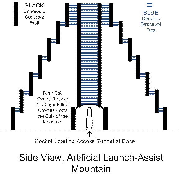
The Rail, and Mounting it on the Mountain
The rail
should be “mushroom shaped” when viewed end-on, similar to what was described
on the main page. This means that a
fairly large amount of storage space inside the rail itself is set aside for
the reaction-mass injectors, and of course, for the contents of these
injectors. The rail itself, here, might
be made of anything practical, safe, and economical, although I would recommend
a mid-grade steel cladding on top and sides, filled with honey-combed aluminum
for resistance to bending of the entire rail, capped off with steel truss-work
on the bottom, for additional bending resistance. The entire rail should then be elevated off
the mountain side for several reasons:
‘1) Obviously we want to keep the
rail as straight as possible, and the mountain side is not going to be uniform,
so we have to even out the lumpiness, ‘2) We want to keep jet and rocket
exhausts away from any flammable vegetation (and poor bunny rabbits, mountain
sheep, hikers, etc.!) on the mountain side, and ‘3) We want to leave space for
misc. infrastructure, etc., to include mechanisms for periodically maintaining
the rail, to include adjustments to the straightness of the rail. Keeping the rail straight (side to side and
up and down) as the mountain erodes, and support structures sag or decay, will
be important. Large hydraulic actuators
or helical-screw mechanisms come to mind for adjustability, although I suppose
there might be other practical choices…
The top
of the rail should have two or more rows of staggered indentations, so that
slow-moving maintenance crawlers could crawl up and down the main rail. Why staggered and doubled or more? Think Cog Railway on Pikes Peak… No matter how vertically you are climbing,
one or the other tooth of the cog wheel and rail are always gripping. The staggered lines of indentations on top of
the large main rail serve to mate with cogged wheels on the slow crawlers. The slow crawler will do one or more of the
following: ‘1) Serve to carry materials up and down (mostly
up) as the rail itself is built in the first place, ‘2) Carry fuel and/or parts and other supplies
for maintenance after the rail is completed, and in preparation for launches,
and ‘3) Grease the rail right before a launch, to reduce friction.
In the
scheme here envisioned, unlike the scheme on the main page, there will be no
hoses between the storage / injection chambers and the combustion / reaction chambers
on the rail-climbing launch-vehicles assembly.
That means that explosive reaction pressures (hot gasses) will want to
blow the reaction chambers right off of the rail. We COULD go and add tremendous anti-expansion C-shaped ribs around these
reaction chambers… Think about your
cast-iron “C” clamp you keep in your garage…
But that means that you are adding a LOT of mass to your ascending
vehicles, which we don’t want. So
instead, we put “phalanges” or lips onto the travelling (bottom) vehicle, and
rollers to the rail assembly, both vertical and horizontal. Now we have forces to countervail against
those that want to blow the reaction chambers right off of the rail, without
heavy reinforcement of the reaction chambers.
I think
at this time a picture (or two or seventy) for clarification is definitely called for…
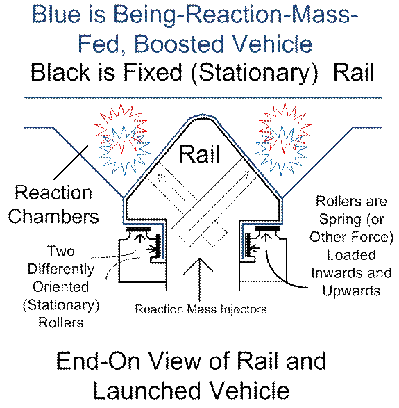
Figure
#1
What is
not totally clear in the above drawing, is the exact purpose of the
rollers. The rollers, by the way, should
either be ‘1A) of small diameter and mass so as to reduce parasitical drag as
they are forced to up-speed-ramp as they vehicle comes into contact, and/or
‘1B) fairly infrequently spaced, say 3 or 4 at most along one vehicle’s length
worth, so as to also reduce parasitical drag (although less of them means less
effectiveness), or ‘2) They should be pre-powered and pre-spinning before they
come into contact with the vehicle, so as to NOT parasitize its movement, and
perhaps even help propel it up the rail.
Pre-spinning the wheels (rollers) can be done (with extra expense and
complexity of course) with electrical or air-pressure driven motors, for
example. Also note that the rollers
would need to be capable of a SLIGHT
degree of motion, say 1/8th to 1/4th of an inch or so,
away from the vehicle phalanges, and pressure-loaded or spring-loaded, and the
leading edges of the travelling (being-boosted) vehicle’s mating “phalanges” or
“lips” or whatever you want to call then, should be equipped with tapered or
even knife-blade-edged, edges to slide between the rollers and the rail.
OK, so, then,
back to the PURPOSE of these rollers in the first place… Depending on the size and shape of the
reaction chambers, we would be forced to deal with the explosive force of hot
gasses trying to deform the reaction chambers and rip them off of the
rail. Then the reaction chambers have to
be made stronger and heavier, which we don’t want. The below drawing focuses in on only ONE side
of the rail and vehicle, and shows the reaction chamber “ballooning out” and
ripping the mating phalanges off of the rail, in the absence of the rollers.
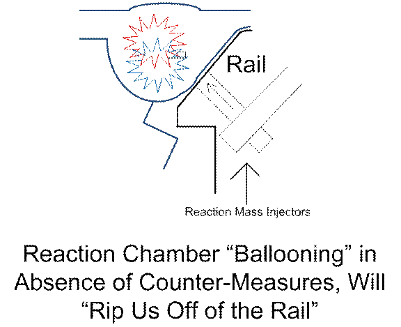
Figure #2
Then
(besides adding extra mass for strength, to the reaction chambers, not a good
choice) we do have one other option:
Make the reaction chambers as cylindrical as possible. If the reaction chamber is ALREADY
balloon-shaped, it cannot balloon!
Assuming fairly uniform strength and rigidity of the chamber walls, of
course… Circles, Spheres, and cylinders
are “nature’s perfect shapes”, resisting deformation (evenly distributing
stresses and strains). So, fill in the
odd corners of the vehicle with a reasonable compromise between strength and
mass… Honey-combed aluminum or hollow
shapes full of struts, for example… And
leave only cylindrical shapes for the reaction chambers. The will reduce (perhaps even eliminate) the
need for the rollers. Here is another
drawing then…
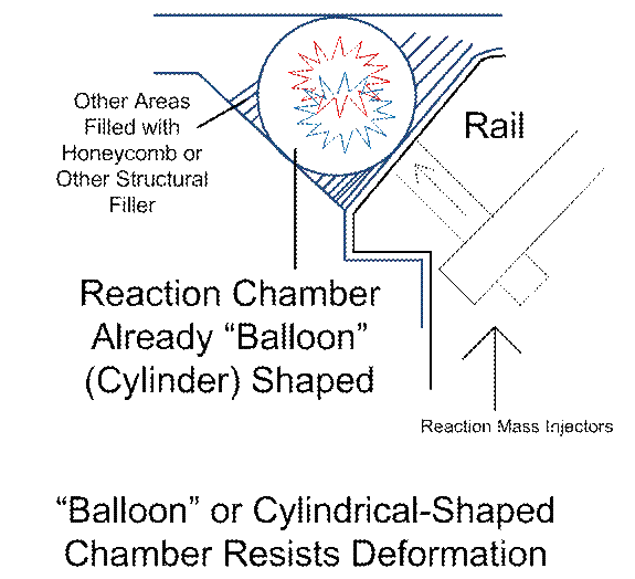
Figure
#3
Now,
what if the economics, physics, and engineering concerns leave us with the
above solution as leading to reaction chambers that are entirely too SMALL (in
relation to the rails), while still being spherical shaped. Please do recall,
our rail will be significantly elevated, there will even be room for the
reaction chambers to droop down well below the rail level. So our reaction chamber can be WAY big if we
want it to be, but we don’t want to have to grow the size of the rail to match
it, if we don’t have too. Well, just
HOW, then, do we “have our cake, and eat it too”, in this case? The secret, here, will be to have, say, a
half-moon shaped (half of a cylinder) reaction chamber, or other
partial-cylindrical shape, sitting right next to the rail. That resists deformation right next to the
rail. Then, at the tips of the half-moon
shape, we have internal (high-temperature-resistant of course) cables or struts
or other tension-resistant internal structural elements that “tie off” the tips
of the half-moon, to NOT allow expansion.
There will be PLENTY of free space between the struts or cables, for hot
gasses to flow in the gaps in between them.
Then, outside of the anti-expansion-reinforced gaps of the tips of the
half-moon, we are free to “grow” the reaction chambers outwards, as much as is
optimal. “Obvious to the casual
observer”, perhaps, but, methinks another drawing is in order…
This
time, we will zoom back out for the bigger, over-all view… Also note that it may or may not be optimal
for hot gasses to flow from one side of the vehicle to the other (to share a
common reactor chamber between the two sides of the vehicle, which straddle the
two sides of the rail). Off of the top
of my head, I would think that it WOULD be desired to maximize the abilities of
the hot gasses to interchange between the two sides, to mix as much as is
possible, to react as much as possible, and to even out the pulsed nature of
the reaction-mass injections, as much as is possible. So we show an internal “reaction chamber
tie-off” to resist expansion, at the TOP of the rail (or, more properly
speaking, at the top of the travelling vehicle, right over the top of the
rail), where the reaction chambers are inter-connected. A solid wall to totally divide two reaction
chambers from one another may make more sense here, but I doubt it (can’t
resist the impulse, sorry… but… Y’all patent trolls are hereby fended off in
both cases!!! J ). Certainly a solid wall would be more massive,
and we aerospace and aspiring aerospace engineering types are NEVER EVER fond
of un-needed mass!!!
OK, then,
the drawing…
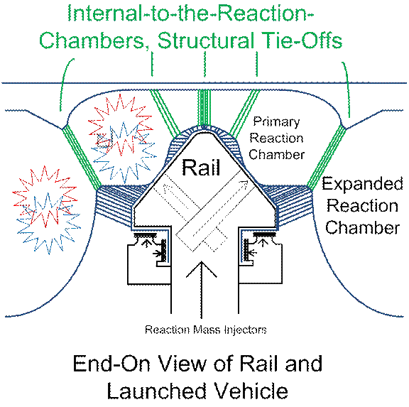
Figure
#4
Please
forgive my less-than-clear verbiage, but the above drawing should hopefully
clarify that internal-to-the-reaction chambers expansive or “ballooning” forces
can be resisted, without the use of massive reinforcement, through the use of
internal tie-offs, and perhaps a few rollers.
We CAN keep things light-weight, but still structurally sound, with a
reaction chamber as shown. The
green-shaded tie-offs, please keep in mind, resist reaction-chamber distortion,
while still permitting the free flow of hot gasses.
The Injected Reaction Masses (and Associated
Concerns)
The
various choices for injected reaction masses have already been fairly
thoroughly described on the main page here.
The only additional notes might be along these lines: In the mountain-side mounted single-rail
approach, it would still be possible to have the primary, being-launched rocket
be firing it engines (at a low throttle rate) and be mated (through a
vibration-resistant and high-temperature-resistant gasket, perhaps made of
asbestos) to the reaction chambers of the launch-assistance (mated)
vehicle. The primary (being-launched)
rocket could even be continuously injecting (relatively) small amounts of
“hypergolic” self-igniting mixtures of, say, hydrazine and nitrogen tetroxide,
to fairly much absolutely insure against “flame out”, or failure for ignition
to be sustained. After all, if the
launch assist methodology injects HUGE amounts of cold, compressed air, and
JP4, or other (safe) low-flammability fuels, “flame out” becomes a real
concern, in all that turbulent flow of fluids.
Keeping the reactants ignited is of real concern. Hypergolics, self-carried by the
being-boosted rocket, are an option, but they are toxic (hard to handle
safely). We all know that the lawyers
don’t like for us to use asbestos either…
Another
choice would be to fill the oxidant injector chambers with a low-flammability
fuel like JP4, for safety. Top each such
JP4 pocket off, on the top, with a layer of (VERY low flammability) wax or foam
or wax-foam blend, to prevent fuel out-gassing.
Over the TOP of the out-gassing prevention layer of foam/wax, we put
gasoline injectors and spark plugs. Mere
seconds before the arrival of the rail-travelling being-boosted vehicle, we
inject a spray or mix of gasoline, and ignite it via spark plug. Now we have a tub of already-barely-burning
fuel, to inject into the reaction chambers, pre-lit to prevent flame-out, awaiting
the arrival of our rocket and carrier.
Slanted-launch here (as opposed to vertical launch on the main page)
makes this approach far more practical.
The
methods available for powering the injections, primary choices being solenoids,
gasoline explosion chambers, and the release of pressurized hydraulic fluids,
to include pressurized air, have already been described on the main page, to
include drawings. They scarcely deserve
to be repeated here.
Also
not needing much further discussion (see main page again), is, what reactants
are most practical? Pressurized air for
the oxidizers, and JP4 or other petroleum fuel for the oxidant, seem optimal to
me. That should be followed up by simple
plain old WATER to reduce fire hazards (temperature of the final exhaust), and
to provide VERY cheap additional reaction mass, as it explodes into steam.
So I
envision staggered injectors with different contents, methods of release, and
timing of release, as the being-injected, travelling vehicle zooms up the
rail. Pressurized air need NOT be
precisely timed, so its release can be triggered by slow-reacting but cheap
solenoids. Who cares if they expend a
bit of their contents before or after their optimal timed release? No fire hazards there, little waste of
precious resources… Oxidant injectors,
on the other hand, need to be more precisely timed in their releases, for both
safety and economy, so they should probably be “gasoline cannons” powered by
gasoline and spark plugs (see main page).
Following the injections of pressurized air and oxidant, timing-wise,
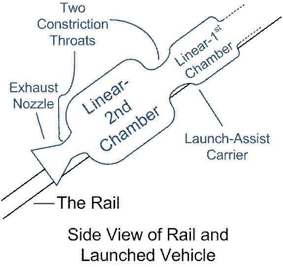
water should be injected. The
being-boosted carrier vehicle should probably have TWO reaction chambers
(linearly), with a constriction throat in between them… The fore-most reaction chamber for dwell
time, pressure, and heat, for combustion to complete, then a constriction
throat to maintain that pressure etc.
Following the constriction throat, another reaction chamber… For the injection of water. The water flashes to steam, creating
additional exhaust pressure. Finally,
one final constriction throat (to maintain dwell time, pressure, etc., for the
water-flashes-to-steam reaction), and then, finally, an exhaust nozzle. The water release mechanism can most likely,
again, be via slow-reacting but inexpensive solenoids. The water should NOT be released in
significant volumes, pre-maturely, which would the fires in the fore-most
reaction chamber, but should primarily be timed to release into the linearly
second reaction chamber. If, however, a
lot of water is released late, spraying upwards into the exhaust nozzle of the
ascending vehicle, then that is no great loss…
It may expend additional propulsive energies onto the ascending vehicle,
and it will SURELY serve to help alleviate any fire hazards!
What,
then, would the side view of the ascending launch-assist carrier vehicle look
like? I am going to ignore the (also
still possible, but probably less practical) scenario under which the
being-boosted rocket has its engines mated fairly directly (via asbestos or other
gasket, etc.) to the assist scheme. That
has been described enough, see main page.
I am going to assume that there will be NO direct coupling of rocket
engines to the assist scheme. Let’s just
focus on the rocket carrier for now.
Here’s a side view, with the launch-assist carrier straddling the rail,
and focusing in, only on the reaction chambers, nozzle, etc.
It is
quite likely that the linearly-secondary (water-flashes-to-steam) reaction
chambers will need to be much larger than the primary combustion chambers, so
that is how they are shown below.
Figure
#5
Summary
/ Rehash of Ideas So Far
A
re-hash and summary of ideas so far discussed on this web page, with a few
extra details and/or variations thrown in, seems to be in order now, before we
move on. What is envisioned here is
reaction masses (pressurized air, JP4 or other inexpensive oxidant, and water)
being contained within the rail, and/or underneath it. The rail-ascending carrier vehicle is
custom-built to specialize in climbing the rail, rapidly, while carrying its
to-be-boosted payload. The carrier
vehicle (to be discussed in detail shortly) will include wings, tail, airflow
control surfaces, landing gear, etc., and two or four jet engines and fuel
tanks out on the wings, so that it can fly and then land conventionally, after
flying off of the upper end of the rail, and discharging it’s payload (which
goes off to fly to orbit). But it’s most
powerful engines will have NO air intake at all, nor compressors, nor
turbines… They will simply be “reaction
chambers” built around the rail-riding center of this carrier vehicle.
These
reaction chambers will need to leave at least some small amount of “air gap”,
yes, between their internal surfaces and where they mate to the rail; machine
tolerances can never be perfect.
Rail-mounted rollers (as discussed above) can help to minimize the
tendency for these mating surfaces to “balloon out” because of escaping
high-pressure gasses. Yes, that’s a bit
differently put than above… But yes, the
reaction container walls deforming under pressure is one concern, and escaping
high-pressure gasses is another concern.
Both causes will “want to” de-mate the mated surface of stationary rail
v/s travelling carrier vehicle. Rollers
can countervail against both tendencies.
Grease on the rail will also help seal these gaps (as well as provide
lubrication).
A very
trivial detail just barely deserves mention, and that is, what about those two
or more staggered rows of depressions or voids carved into the tops of the
rails? The ones that should be added for
slow-moving construction and maintenance crawlers? When the sealing surface of the fast carrier
vehicle meets these voids, will this not allow opportunities for high-pressure
gasses to escape? Well, yes, if we are
totally stupid, and make the carrier vehicle mating surface be not wide enough
at these spots… The solution is simple
and obvious: Make the mating walls of
the reaction chambers, at these spots (leading edge of the carrier), be wide
enough to straddle over an entire void, plus safety margin.
But
while we are discussing these two or more rows of rail-top voids, one other
idea deserves to be briefly mentioned.
That is as follows: The very
first few yards, meters, or tens of yards of the carrier vehicle’s journey
upwards may NOT be most optimally or economically powered by the main ascension
methods here described. Rather, to get
“up to speed” for the first (??) 50 MPH or so, before the
injected-reaction-mass method becomes primary, a slower boost method might be
used, that uses these same staggered rail-top rows of indentations, and
mechanical energy. This short boost
stage “train engine” (not part of the carrier vehicle) might use an internal
combustion engine, a store of compressed air and air motors, stored energy in a
flywheel, or even electric motors… I am
not sure what makes the most sense here.
What all of these methods would have in common, though, is the use of
cog wheels that mate to the staggered rows of rail-top indentations, and that
such a boost “train engine” would have to be built to withstand the heat and
pressure of the being-turned-on, main propulsion method.
When
the boost “train engine” and carrier vehicle part ways from one another, it
might also be a good thing to do (with large air pressure pistons or mechanical
springs, or other method), to forcibly separate one from the other, recoil
style. This imparts additional
upwards-directed power to the carrier, and gets the booster “train engine” out
of harm’s way, faster.
The
mix of reaction masses to be injected, from an economic and pollutants
standpoint both, should almost definitely be way heavily biased towards a large
surplus of compressed air (skimpy on the oxidants). The injectors should be “goose necked” at the
tips, just barely inside the surface of the rail, so that their kinetic /
momentum energies are optimally directed towards the direction of travel of the
carrier. Search for “goose neck” on the
main page… Just one drawing might be
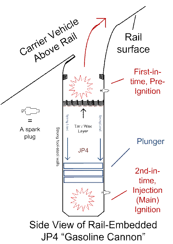
warranted here, to show a “gasoline cannon” (gasoline powered oxidant
injector), with all the trimmings. As
mentioned before, this might be optimal:
A gasoline explosion chamber (auto-engine style), main oxidant contents,
a layer of low-flammability, low-outgassing wax/tar blend to preserve the main contents
during the hours or days of pre-launch preparation, and an air-gap with
gasoline-spray and spark plugs to pre-ignite the top of the fuel injector,
seconds (or fractions of a second) before the carrier vehicle arrives. The fuel pot is pre-ignited (starting to
burn) before the carrier arrives, and then the entire pot of burning fuel is
injected (cannon-shot) at the optimal time, into the reaction chamber of the
ascending carrier.
Figure
#6
The carrier
vehicle, as mentioned, has (on it main rail-centered engine) no air intake,
other than the injectors that are rail-mounted.
No compressors, no turbines, keep it simple… A front-to-rear varying-profile giant
reaction chamber, basically… A fairly
small front reaction chamber where the oxidants are injected, then a long
section where the reaction chamber is skinny (the long skinny section serving
as “constriction throat” to keep high heat and pressure, or “dwell time” for
combustion to complete), then a larger reaction chamber where the water starts
to be injected. This second chamber will
allow at least some water to flash to steam, which gives us more propulsive
power, This reaction chamber is followed
by another constriction throat (to provide dwell time / heat / pressure for at
least some water to flash to steam) Finally, a nozzle area where water keeps on
being injected (for fire suppression and additional reaction mass). All mass injectors, not just the oxidant
injectors, should be “goose necked” at the rail surface, to optimally re-direct
their kinetic / momentum energies.
Where
possible, in the name of saving costs and weight, airflow-control structures
(wings and tail), which also serve as structural forces-bearing elements
(“weight-bearing”, loosely speaking) will want to double up as reaction-chamber
walls. So perhaps it would make sense
for the first reaction chamber (smaller, where oxidants are injected) to come
before the primary front wings, and for a long, skinny, first constriction
throat (are where combustion can proceed, before combustion-dampening water
injection starts) to coincide with front wings.
Certainly it makes sense for these wings to be mounted well below the
level of the rail, so that the wingtops (close to the fuselage) can serve to
double up as the bottom of the reaction chamber, in this area. After that, water injection begins, and the
reaction chambers balloon back up to a large cross-sectional area. Finally, the reaction chamber narrows back
down, with the bottom of this second “constriction throat” doubling with the
tail surfaces (once again, the tail surface is mounted well below rail level,
just like the front wings). The nozzle
area can stick out the rear of the carrier vehicle, past the tail fins. If this is a bit unstable, perhaps the entire
vehicle can be made to be very long (which serves to help capture more injected
reaction masses anyway, if their timed releases are a bit sloppy, and/or speeds
get to be large). Perhaps front-mounted
canard wings can help to compensate for less-that-optimal tail configuration…
In
passing, note also that high speeds are an enemy of well-timed reaction mass
injections, and of economics, and of wear and tear on your whole engineering
scheme. Perhaps best would be for the
whole scheme to max out at 100, 150 mph or so, with relatively low rates of
reaction mass injections, till the very last stages of the upwards journey,
where the frequency of mass injections could increase, and boost speeds up to
(???) 200, 330, or even more, mph.
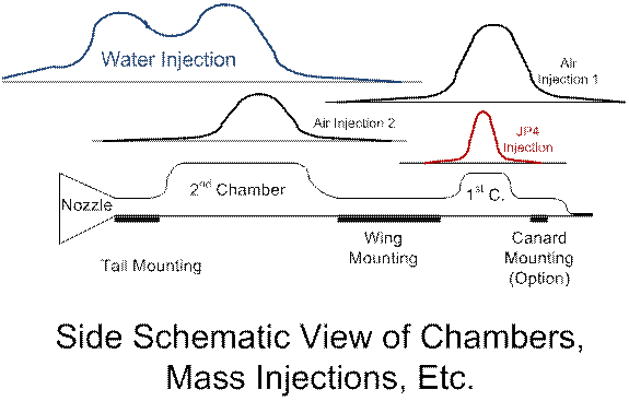
Here is
a schematic diagram to generally illustrate the idea of reaction chamber size
v/s length profile, wing and tail mounting surfaces, and 3 bell curves to
illustrate the timing of reaction mass injections. JP4 (or other oxidant) is precious, so it
deserves tight (but expensive) timed releases; hence a narrow bell curve. Compressed air and water are cheap, so we use
cheaper, slower-reacting solenoids to control their release. This is just a schematic concept drawing; the
tile of the rail, and the rail itself, are omitted. We just want to see reaction chamber size v/s
airflow-control surfaces v/s what is injected where. Note, again, a bit of wasted air and water is
cheap…
Figure
#7
The
above drawing shows only one possible scheme of reaction-mass injections, which
may or may not be optimal. More tightly
controlled releases of reaction masses, or more of them, may or may not make
sense, but obviously, more complexity, as usual, makes for more expenses, and
more points of failure. If one thinks
about what is diagrammed above, while keeping in mind that the rail has to
divide the bottom half of the entire carrier vehicle body, then one other thing
comes to mind: the wing and
tail-mounting, “weight-bearing” structures are split in half, right down the
middle of the fuselage. So at these
locations, the TOPS of the fuselage (over the tops of the constriction areas of
the long reaction chamber) would have to be structurally reinforced (heavy) as
well, for the whole structure to hold together.
Thus, it makes sense for constriction areas to coincide with wings and
tails areas.
The
Launched Carrier Vehicle, Details
The
launched carrier vehicle will be awarded the “ugliest flying machine ever”,
perhaps, but so be it! One launch rail
could accommodate many different kinds of carriers plus launched vehicles. Let’s just describe a very few,
most-plausible ones. First, the carrier… Let us assume that in this case, it will
launch a rocket, probably a multi-stage rocket, that will then climb to
orbit. The rocket will be center-mounted
on the carrier, to keep things symmetrical and balanced. The carrier will be equipped to fly itself
back to a landing strip after the rocket takes off, off of the back of the
carrier. So the carrier will need wings,
of course… One possible approach has
already been described... We would
probably be best off with TWO tall tail fins in the rear, leaving a gap for
rocket exhaust in between them. Jet
engines and fuel tanks on the wings, to provide a SMALL amount of additional
propulsion during launch-assist phase, but mostly for powering it so as to land
itself after the launch-assisting mission.
Since it will need to be re-mounted to the launch rail for the next flight,
it might perhaps need to be constructed modularly, for easy dis-assembly and
re-assembly.
Landing
gear perhaps follow one of 3 different schemes: ‘1) The usual tripod, one in the front (it would
have to be long-legged, folding up into the body during rail launch, over the
front center), and 2 on the wings, where one may or may not bother to spend the
extra money to allow them to fold up into the body of the vehicle. The carrier’s journey is short, so it may not
make sense to bother to fold these 2 points of the landing gear up into the body. ‘2) An
unconventional approach could be used, with 4 points for wheels, 2 on the front
main wings, and 2 on the tail (not centered).
Now we leave ALL of them non-folded, saving expenses. ‘3)
Canard front wings could also be equipped with non-centered landing
gear, as part of the mix. If the carrier
vehicle is going to be ridiculously long and/or modular (dis-assemble-able for
easy re-mounting on the launch rail), then a total of 6 (SIX) landing wheels
points, 2 canard, 2 main wing, 2 tail-mounted, may make sense.
The
rocket to be launched will want to be center-mounted for symmetry. It will want to be mounted some distance up
away from the fuselage of the carrier for clearance. Many different schemes are possible. It might be best to have the rocket start
it’s burn well before the 2 craft part ways.
To keep the weight of the rocket centered over the weight-bearing main
wings, it would probably be best to mount the center of gravity of the rocket
right over the main wings. Right before
the 2 vehicles part ways (obviously out in free air, well after departure off
of the end of the rail), the carrier should apply full power, increase its
angle of attack, and put itself into a stall or near stall. As it approaches the departure point, it
would probably be best to have the rear mounting point (between carrier and
rocket) be up on hydraulic jacks, so that rocket exhaust will gain clearance
from the carrier. Having front AND rear
(and middle?) mounting points ALL be on hydraulic jacks, might even be warranted,
to decrease air resistance for the short mated flight, who knows... I am betting that rear jacks only, makes more
sense.
A
structural support “bed” for the rocket probably also makes sense, especially
if we use the hydraulic jack(s) option.
It would be part of the carrier, but would swivel (move) with the
rocket, out at the end of the hydraulic jack(s). A
drawing is in order, then, of course…
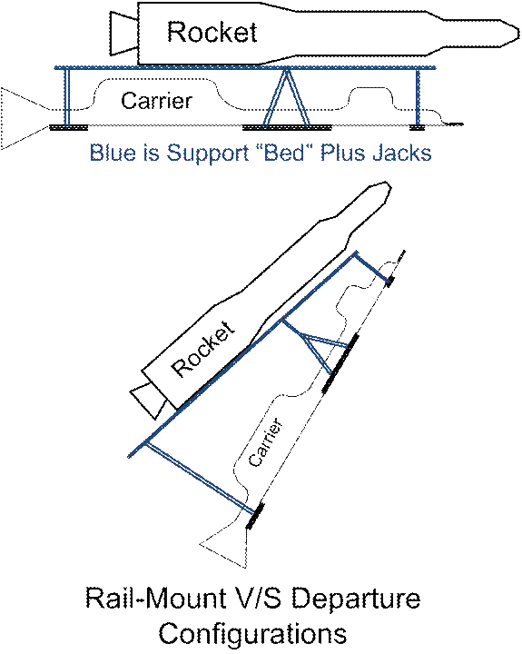
Figure
#8
Various
variations of the above are possible, of course (number of mounting points and
how many of them are on jacks). The
above is shown with 3 (three) mounting points along the length of the assembly,
with 2 of the 3 on jacks.
Other
variations are possible as well. We
could, for instance, put THREE vehicles together… A carrier similar to what has already been
described above, plus an air-breathing middle variable-engine-geometry vehicle
as described on the main page (using pyrometric-ceramic-based turbine blades,
for example). Then on top of THAT
vehicle finally, a small rocket. The
middle vehicle in this scheme would travel high into the stratosphere before
launching a single-stage rocket. One of
the few differences here would be that the carrier, in this scheme, would
likely need only ONE, centered vertical tail fin instead of two (not needing
clearance from a center-launched being-launched rocket’s exhaust).
Building
Your Own Mountain
Now
suppose you want to build your rail-launch assembly in an optimal southern-USA
area (southern tip of Florida, Texas Brownsville area) where you can launch out
eastwards over the open ocean, and you have no mountain. Build your own! What would such a thing look like? I think it would look like this: At the base, a large circular vertical wall
of reinforced concrete. Fill the whole
area with dirt. Set back a few yards
from the top of that wall, buried down into the dirt for a few yards, and tied
via concrete struts to the first wall, another wall (smaller diameter
circle). Repeat! Unlike hollow buildings, such a structure
could inexpensively be built 4, 5, or 10,000 feet tall. If the dirt settles a bit over time, you just
fill in some more at the openings between the larger circular wall and the
smaller one. Even if the tower leans a
bit over time, as dirt collapses or settles, the rail can be adjusted to keep
it straight. A “conical pyramid” or
“tapered beehive” structure of this sort won’t topple over in a hurricane, like
a building might, because of its shape.
Also, if the outermost periphery of such a structure is made of sand,
clay, earth, gravel, rocks, etc., which is less susceptible to collapse than
garbage is, AND the appropriate levels of clay, plastic, and plumbing for the
removal and use (recycling) of methane, and toxic liquids is added, using all that
we have learned of modern “garbology”…
Keeping in mind we can always keep topping it off as it collapses… Then there is no reason why our
rocket-launching artificial mountain cannot double up as a sanitary
landfill. If that is not politically
feasible because of the “NIMBYs” (“Not In My Back Yard”) and the BANANAs
(“Build Absolutely Nothing Anywhere Near Anything”), then at the VERY least,
mining tailings and canal and ship-channel dredging disposal materials might be
more politically plausible.
Oh, one
last point before moving on… Not to
belabor what should be obvious in the first place… If we’re going to build a rail up the side of
our artificial mountain anyway, as its primary purpose of said mountain… Then the rail-top needs to be topped off by
the previously discussed two or more rows of staggered indentations for
slow-crawling building and maintenance crawlers. We might as well make these rows of
indentations strong enough to support industrial-scale crawlers that transport
the dirt, rocks, mine-tailings, and/or garbage that fills up the guts of the
mountain in the first place.
Alternate
Implementation – Tow Cables
On
further consideration, I still do believe that the entire idea of
reaction-mass-injectors-embedded launch rails is plausible, but probably not
economically or engineering-wise optimal.
Accordingly, as usual, this web site will retain the already-described
ideas, in the name of fending off the patent trolls, just in case I am wrong,
and the already-described ideas ARE optimal. However, here are the reasons why the
reaction-mass injectors idea should be bypassed, in favor of a much simpler
rail or set of rails, and tow cable(s) alone:
‘1) The rail with embedded
reaction-mass injectors needs to be much larger than otherwise, and therefore
more expensive, ‘2) such rail also needs
to be precisely machined to tight tolerances, as does also the rail-travelling,
mated vehicle, in order to not spill large amounts of reaction mass, which VASTLY
increases costs, ‘3) a simpler rail (with looser mechanical tolerances being
acceptable) also requires less precision alignment and maintenance, and finally,
‘4) a base carrier vehicle that is cable-towed (to carry a rocket to higher
altitudes, being the primary application or intention) can be non-specialized,
carrying very little weight that is specially adapted to the tow-cable-assisted
launch, and so, such a vehicle could be equipped with fairly standard jet
engines, allowing it to ascend 40,000 or 60,000 feet, say, before discharging
its payload. Compare that to a
specialized carrier vehicle with specialized main engines that need to be
rail-injected, and the tow-cable approach becomes the (fairly) obviously better
choice… Unless technology changes! In which case I am fending off all the patent
trolls in either case! Nanny, nanny,
noo-nah, neener-neener-neener! Phhhttthhh!!! … (OK,
I am going to go back to being mature now J ).
So then,
let’s write a few words about a simpler rail or set of rails, and tow cables
that tow your assembly of vehicles up the side of the mountain. The assembly could be a jet aircraft carrying
a rocket, yes, or a “catamaran aircraft” (double-fuselage aircraft) rocket
carrier in the style of “Stratolaunch”, see http://www.stratolaunch.com/ … Or it
could be a rocket on a rocket-mounting “bed”, where the mounting “bed” is just
discarded to tumble down on the far side of the mountain, with the rocket
itself firing up as it approaches the end of the rail on the mountain-top. In either case, tow cables tow the assembly
up the mountain, attaining high speed (200, 300, 400 mph) before “slipping the
surly bonds of Earth”, increasing payloads launched, and/or decreasing costs.
With
today’s state of technology and costs, woven-steel tow cables are probably
going to be your best choice. In the
future, nanotech carbon cables may become a better choice… Almost certainly such carbon-nanotech-based
cables will become practical for this tow-cable mission here, FAR before they
become practical for the “space elevator”! See http://en.wikipedia.org/wiki/Space_elevator
...
The
tow-cable to towed-vehicle interface can be fairly simple. Imagine a ball (twice the diameter of the
cable, say) firmly attached to a “funnel” inside the front of the body of the
towed vehicle. The constricted neck of
the funnel points forward, and there’s a slot (of width matching cable
diameter) in the tapering-down funnel. The slot points down if the tow cable is
underneath the launch-injection rail-top point, or off to the side if the cable
is side-mounted. One could even
entertain notions of TWO slots and TWO tow cables on TWO sides, with the
cables-tip ball being two weakly-magnetically-mated half-spheres, to be
separated (split) at ejection time. At
ejection time, the cable-tip sphere (or hemispheres) tear out of the
funnel-tip, and bring the end of the cable(s) out of the funnel slot(s), and
all is demated. Simple! The funnel obviously needs to be strong, and
strongly mated to the body of the towed vehicle, but that does NOT add much to
the specialized mass of the towed vehicle (unlike a specialized engine for
taking up reaction mass from a specialized and expensive rail).
The
power to pull the tow cable(s) can come from a power station at mountain-top
(less cable mass and expense, more costs to equip and maintain the power
station), at the far side of the mountain-bottom (more cable, less of a sharp
bend radius in the cable at mountain-top, more real estate costs), or at the
near-side of the mountain-bottom (more cable again, 180 degree cable
turn-around at the top, meaning sharp bend radius or large wheel with high
costs and high spin-moment of inertia).
Various possibilities exist here…
I suspect mounting the power station on the far side of the mountain,
just past the top, would be best.
Alternately, the cable itself could be entirely eliminated, with energy
imparted to the ascending carrier through (???) along-the-rail-distributed air
motors, internal combustion motors, electric motors,
electromagnetic-rail-gun-type energies imparted through capacitive discharge,
etc., but I think such schemes to be all too expensive; tow cable(s) sound good
to me! Tow cable(s) allow one to
concentrate expenses on ONE central power station, is the obvious advantage…
So how
do we pull on this rope? Again, power
schemes run the whole gamut… air motors,
internal combustion motors, electric motors, electromagnetic-rail-gun-type
energies imparted through capacitive discharge, etc. … OK, I am getting repetitive! Well, then, how about weasels running around
an exercise wheel?!?! OK, must be
serious, otherwise the lawyers will find more excuses to enable the patent
trolls, and to dismiss my selflessly-contributed ideas…
Most
practical, I believe, in the balance, is…
In light of the “no-free-lunch” principles that we as engineers
intuitively just KNOW, in our guts… ANY
time you convert ANY kind of useful power to some other form of useful power,
there will be losses of useful energy along the way, to inefficiencies… Nothing is ever-ever perfect; certainly not
energy conversion schemes! Then, spin
energy is spin energy is spin energy, let’s keep it that way. We are looking at fly-wheels, and electric
motors and generators, and either slip-clutches or electro-magnetic hysteresis
brakes.
OK,
follow me through here… Time-line-wise,
we load up our assembly of launch vehicle plus carrier, at the base of the
rail. All systems go… Test it good!
All right, ready to go. Slowly
crawl up the rail (1/2, 2/3 of the mountain side, whatever makes sense, under
the most efficient and sensible power scheme) to the
start-of-acceleration-point. Hook up the
tow cable(s). Energies pour in (to the
perhaps-already-spinning flywheel, boosting it further). Electric or other motors previously start
spinning your giant flywheel, yes, duh, sorry to point out the obvious… Launch time starts… Additional methods (inflating airbag(s), air
piston(s) energized, mechanical springs released, whatever make sense) kick in,
initial movement is initiated. Flywheel
energy (to the tow cable(s)) kicks in, time-tapered-wise, via a mechanical friction-clutch
(see http://en.wikipedia.org/wiki/Clutch
). Now this is a crude and barbaric
method, I do believe, and is going to waste untold energies to be wasted via
friction (and friction-induced heat), as the flywheel suddenly starts pulling
on the tow cable(s). Frication is going
to create waste heat and require frequent friction-surface replacements (think
brake pads on your favorite chariot as it sits there in your driveway by your
palatial mansion; I sure hope it is anywhere nearly as large as mine! J )!
The
less-barbaric method of slowly (time-wise-staggered, and smoothly ramping)
imparting tow-cable-pulling-energies from your stored flywheel energy, is to transfer
spin energy via electromagnetic hysteresis brakes-type (mechanical
contact-less) forces, see http://en.wikipedia.org/wiki/Electromagnetic_brake
and/or http://en.wikipedia.org/wiki/Electromagnetic_clutch
and/or http://en.wikipedia.org/wiki/Eddy_current_brake
. And certainly see http://en.wikipedia.org/wiki/Flywheel_energy_storage
...
At a
high level, what would a very large cable-pulling apparatus look like, in our
scheme here? It might look like
this: A central sleeve bearing running
right down the central axis of the whole assembly, plus perhaps here and there,
for support to prevent gravity from bending the entire assembly, on the bottom
side, more bearings sliding against the outermost spinning surfaces. Some bearings may be mechanical, some
electromagnetic, and some may be “air bearings” or fluid bearings, see http://en.wikipedia.org/wiki/Air_bearings
. The flywheel-containing cavity would
almost definitely be vacuum-filled to reduce friction. See the drawing below… From left to right, an electric motor to pour
energy into the system (AC or DC electrical power to mechanical spin energy), a
flywheel (which may or may not contain internal motors and/or generators to
trade electrical power v/s spin energies back and forth), an electromagnetic
clutch (or other form of clutch) for coupling and de-coupling spin-power-input-side
v/s spin-power-output side, then a cable-pulling wheel, and finally an electric
generator.
Well
before launch time, the flywheel is spun up.
The clutch is dis-engaged (cable is not being pulled on). Optionally, some OTHER source of SLOW spin
energy might be put into the cable-pulling side (not shown below) to slowly
bring the to-be-launched vehicles assembly part-ways up the mountain-side, to
the start-of-sudden-acceleration point.
When that point is reached (by whatever is the most economical method),
the clutch will slowly engage more and more, starting to pull on the
cable. Notice that the cavity in the
cable-pulling wheel is wide at the base (close to the central spin axis), and
tapered narrower further out. As the
cable fills the cavity, then the amount of linear distance pulled on the cable,
per revolution of the wheel, will increase.
This will help accelerate the being-pulled vehicles to ever-greater
speeds towards the mountain-top, which is exactly what we want. This increasing linear pull-speed will happen
as the cable “piles up” in the center of the cable-pull-pulley, whatever the
shape of the cavity is. How fast the
cable “piles up” is partly a function of cable diameter, and so it is possible
that I am wrong… Perhaps (depending on
cable diameter and desired pull speeds, the speed of ramp-up of the spin speed
of the pull wheel, etc., the shape of the cable cavity might be neutral, or
even inverted from what is shown. In any
case, note that it is a useful control variable.
At the
time that the vehicles assembly is thrown off of the top tip of the
mountain-top rail, the cable decouples, and now you are left with a huge amount
of spin energy in the cable-pulling wheel, plus all of the cable. Now you can do one of at least 3 things: ‘1)
Fire up your generator on the cable-pulling-wheel-side, to spin down the
cable-pulling wheel to zero speed, in preparation for the next launch, of
course. Since the next launch is 3
months from now, dump the recovered electrical energy back out onto the grid,
or ‘2) next launch being ½ day from now, we dump the recovered energy back into
the flywheel side in preparation for that launch, or ‘3) (probably the most
often used) dump the energy back into the flywheel and store it there to be
dumped slowly back onto the grid as the grid needs more power, and as you
figure out, just exactly when IS our next launch, anyway? Earn a few dollars on the side by selling
your energy-smoothing services to the utility company…
A few
details come to mind that might be worth mentioning: The inertia in the cable itself will want to
un-wind the cable off of the cable-pulling wheel, if we decelerate the wheel
too rapidly (post-launch). To prevent
this problem, if we are using (ferrous, magnetic) steel cable, we can embed
electromagnets into the bottom and/or sides of the cable-pulling wheel. The electromagnets are energized, grabbing /
securing the cables, during deceleration time.
If carbon nanotech cables are used instead, then ‘1) embed them with
iron particles to make them magnetically grab-able, ‘2) run this carbon-based
cable side-by-side secured or interwoven with steel cable strands for the same
purpose, or ‘3) find a more purely mechanical method of securing the cable
during pulley deceleration, such as extensible fingers that, post-launch,
extend out and pull down on the top of your rolled-up cable, within the
cable-pulling wheel cavity.
Control
of internal electronics within spinning assemblies will probably be via radio
waves. Electrical energy transfer into
and out of spinning assemblies can be via carbon brushes; see http://en.wikipedia.org/wiki/Carbon_brush
... This is a proven technology that has
been around for a long-long time. These
can be placed side-by-side along the side of any external support bearings, if
they are needed.
OK then,
finally a top-level schematic drawing…
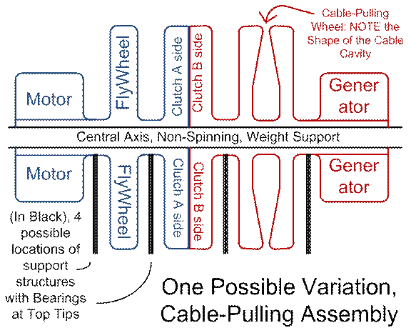
Figure
#9
Various
variations of the above are, as usual, possible. The central non-spinning axis might be one
giant big solid sliding-bearing, or it might be, at least in some areas, like
two pipes, one inside the other, rotating at different speeds. The flywheel might be firmly mated to the
spinning central bearing, but it would more likely be able to rotate at a
different speed than what couples it to the motor (it would be likely to
contain its own integrated motor(s) and generator(s), so that it can rotate at
a different speed from the central axis, if need be).
The
above drawing shows the two faces of the gripping surfaces (be they
friction-mated, or more likely, electromagnetically mated) as being flat-faced,
or vertical, inside the clutch. This has
the advantage of simplicity, but it has the disadvantage of varying linear
slip-speeds as one travels from one radius to another. This makes the engineering more complicated
(difficult). More likely, this slip
surface will be arranged horizontally, as shown below, in a close-up of the
alternate arrangement. This makes for a
mated-surfaces interface area (grip or slip area) whose linear travel speed is
uniform at a given moment in time.
Figure
#10
As one
examines the above drawing, one might consider that there would be so much
space there on the flywheel side of the clutch I/F (Inter-Face) surfaces area,
inside these I/F surfaces, that the drive motor might as well be located
there. Integrating the clutch and motor
here is probably a good idea…
I do not
feel as if I am likely to have any special ideas worth documenting, in the
categories of giant flywheels, motors, generators, or cable-pulling pulleys,
other than what simple and obvious ideas have already been discussed
above. However, I am an electrical
engineer, and I have dabbled in various components and design techniques that
might relate to the design of an energy-efficient electromagnetic clutch (as is
applied to this somewhat specialized application here). This is all, mostly, off of the top of my
head, and might contain mistakes here and there, a bit, but should mostly,
basically, be correct. If you see any
goofs, here, reader, PLEASE speak up, write to me at RocketSlinger@SBCGlobal.net
… I ***WILL*** give credit to your
contributions, if you allow me to, I do try to hold me ego in check…
First
off, consider a time-v/s-spin-speed profile.
If we are going to want to be energy-efficient (recycle as much energy
as possible), we won’t just want to “grind one set of electromagnetic fields
against another” and waste the heat thus generated, as in an electromagnetic
hysteresis brake, then we will want to arrange electromagnets on both sides of
the “grip or slip” area. There will be
DC-powered electromagnets in a radial band (or bands) on one side, mated to
un-powered electromagnetic (“pick up”) coils on the other side. Which side has the DC-powered electromagnets,
v/s which side has the un-powered electromagnets, will alternate back and
forth, as we travel up and down the clutch, parallel to the axis (I am going
with figure #10 arrangement here). When
the clutch is entirely disengaged (“slip mode”), there will be no DC power
applied to the can-be-powered-electromagnets sides, at all. More and more of them will be turned on as
the clutch is gradually engaged. As they
are turned on, the magnetically-mated passive electromagnets will react to the
constantly changing N-S-N-S-N-S (North and South alternating) magnetic fields
that they pick up, from the DC-powered side, and create AC on the pick-up
side. From band to band (ring to ring)
we alternate which side is powered by DC, see, and which side creates AC. Each side then grabs power from the other,
full-wave rectifies its induced AC, and creates DC (for basic linear AC to DC
technology, see http://en.wikipedia.org/wiki/AC/DC_(electricity)
, look up full-wave rectifier, diode rectifier, capacitive filtering, etc.; I
have nothing special here to add, other than, a poorly regulated AC to DC scheme
will work fine for this application here).
Each side powers the other, as the two sides of the slip-v/s-grip
surfaces magnetically mate. AC is picked
up, and DC is used to power the coils.
Matched pairs of power-swapping magnetic fields can slowly be turned on
(time-staggered as to how many mated bands are turned on), for smoothly ramping
up the cable-pulling pulley.
Well
anyway, if we are going to keep things efficient, which is always good, then
the mating electromagnetic fields must always be CHANGING on the pick-up side,
which means that the being-accelerated side of the clutch will NEVER fully
catch up in spin speed, to the being-slowed-down side (flywheel and motor side). After the whole show is over, that is, we
will still be partially in “slip” mode, we will never go fully to 100%-mated
“grip” mode (in the name of efficiency).
So then finally here is our spin-speeds-being-traded-off, v/s time
profile.
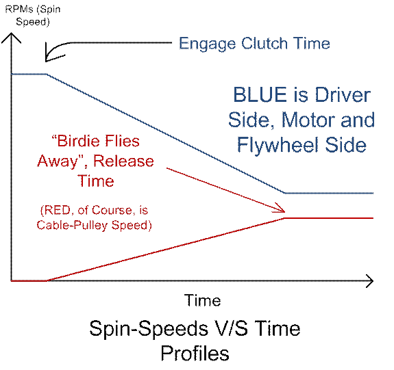
Figure
#11
So as
one can see, as time goes by, the speed differential between the two sides is
cut way down, but never becomes zero (if, as I mentioned, we want to maintain
alternating magnetic fields for efficiency).
However, if we study up on our design theories for transformers… And a transformer basically is what we have
on the pick-up side where we create AC, or, more properly speaking, in the
entire assembly from driver side to driven side… Then we will find that transformer designs
(for efficient power transfer at least, which is what we want here) need to be
optimized for a given frequency. Core
design, windings design, etc. … OK, now I do confess, all the fanciness to
follow, may or may not really be warranted, or be justified economically, but,
I do want to show off my electrical engineering talents here, while we are also
possibly fending off the patent trolls! I
am Sparky, here me roar… AKA, I ***AM***
the un-intentional arc welder extraordinaire!!!
OK, back to work now…
So our transformer (N-S-N-S alternating-fields switching-speed) frequency is going to vary with the spin-speed differential between the two sides of the clutch, right? How do we handle that and try to stabilize the frequency a bit? To optimize the design efficiency, that is? Well, consider the below flattened view of the face of the driver side of the clutch (actually, could be either side). Let us say that “N” is a “North” magnetic face (tip of an electromagnet), and “S” of course is South. “PU” is for “Pick-Up”, where we pick up power from the opposite side. On both the driver side and on the driven side, since we are talking speed DIFFERENTIAL and not absolute speeds here, they are able to (individually, on most of the electromagnets, if not ALL of them) be switched, “N” or “S” polarity. At high spin-speed differentials (clutch engage time), we want to turn DOWN the frequency of the N-S-N-S fields, and so we have long runs of N-N-N-N and then long runs of S-S-S-S… As time goes by, spin-speed differentials decrease, and so we switch more and more towards N-S-N-S-N-S-N-S, to “up” the frequency (compensate for lower spin-speed differentials). Consider then the below drawing… “PU” for “Pick Up” is shown to remind us of the intermixed bands on both driver and driven side.

Figure
#12
And just
HOW does one switch an electromagnet (DC-powered) from “N” pole to “S” pole and
back? By polarity of DC current. Current flows one way, you have a “N” pole at
the exposed tip, and vice versa. In
reality, the I/F between clutch faces might (probably would be) “rippled”
looking, protrusions on one side inserted into slots on the other side, so that
the electromagnets (powered v/s pick-up sides) could have maximal side-to-side
rather than tip-to-tip exposure, in the name of efficiency, but that can be ignored
in simplified drawings. … Well anyway, one applies one polarity of DC
current for a while, as makes sense, and then comes switching time. Power the coil OFF completely for at least
fractions of a second, it not more (and add a “snubber diode” to kill inductive
“flyback”, to boot). Inductance inherent
to electromagnets, that is, does NOT allow us to instantaneously change
currents; if we try, the sparks will fly! THEN go and apply the opposite polarity of DC
current flow (reverse the “N” pole to “S” pole). Electromechanical relays can be used as
switches (plus side, not much, minus side, switching speeds and moving parts
mean they can wear out), Or, we can use
“N” and “P” channel MOSFETS (plus sides, higher reliability due to, no moving
parts, and, higher switching speeds). I
favor the FETs in all applications where they can be made to work decently,
which includes the one at hand…
For your
“N” channel FETs, they are good for adding your switch to GND (ground, 0 VDC) switched
connection on one end of the coil, and your “P” channel FET to the other
end. If we want to switch current in a
bi-directional manner, we want a “P” FET to “+” VDC and an “N” FET to GND (AKA
“-“ VDC supply) at both ends of the coil.
Not to go on all day about this boring stuff, but here is your diagram,
complete with “snubber” diodes to kill fly-back. (OK a tiny bit of boringness, to turn an
N-FET on, you want about 3 VDC or more of G to S (Gate to Source) voltage, and
to turn a P-channel FET on, you want a 3 VDC or more of MINUS G to S, AKA plus
3 VDC or more of S to G (opposite polarity).
OK, your drawing then…
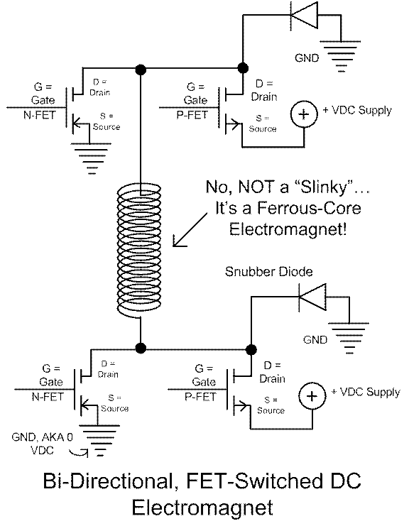
Figure
#13
For one
polarity of DC flow, turn on the “P” FET on one end, and the “N” FET on the
other end… For the opposite, do the
opposite! As an after-thought, come to
think of it, in the above-shown scheme, the “snubber diodes” (AKA fly-back
suppressing diodes) are NOT really needed, because the inherent “body diodes”
inside the un-powered N-FET, at the N-FET-turned-off end, will do the job, with
any decent power N-FET, anyway.
A SMALL
amount of R-C filtering at the gates of the FETs might be nice, for smoothing
out sudden voltage and current spikes, but we don’t want to do too much of
that, or the FETs might get fried by spending too much time (dissipating too
much heat) in their “linear” modes, half-turned-on, and half-turned-off. Also note, we are going to ramp up the “grab
factor” (strength of coupling between the two sides of the clutch, and ramp-up
rate of the cable-pulling pulley), by time-sequencing the number of mated bands
of powered electromagnets (one side) and pick-up magnets (on the other
side). At start-up, start the coupling
one by one, adding more mated (energized) bands as you go along. That should give a reasonable degree of
control. If it is NOT enough control,
and we get bad “chattering” (shock, vibrations) as these are time-sequenced in
turn-on, then we can ALSO go and taper the degree of turn-on of individual
powered-side DC electromagnets, by doing PWM (Pulse Width Modulation or duty
cycle modulation) on the gates to the FETs.
Enough
EE geek-talk for now? Well, maybe
not… I am not sure if the AC energies
created on the pick-up sides (and converted to DC to power the DC
electromagnets) are going to be in excess of what the DC side needs, or
not. If there is a SIGNIFICANT amount of
excess AC power created, how do we recycle it?
Especially if (inevitably) the AC power created is going to be a
hard-to-handle, wild mix of different frequencies, coming from different bands
of electromagnets and different spin-speeds over time? I am not sure what recycling method would
make sense, if any method makes sense, here (ultimately, in terms of economics,
of course). Suggestions? Send them to me at RocketSlinger@SBCGlobal.net
… In the meantime, I am going to say, I
suspect any such excess power would be on the smallish side, and would best be
dumped to power resistors (turned to waste heat). There are now-becoming-practical methods of
recovering useful energy from surfaces with a heat differential across said
surface, I might add, and we MIGHT want to see if we can then recover some
power off of the heat-wasting power resistors…
But I doubt that it would be worth bothering with. Let us move on for now, then…
UPDATE:
Upon re-considering, I suspect any excess AC picked-up power can easily,
efficiently be turned to DC (through switched-AC-power-supplies type MOSFETs,
see below), and be collected & recycled (dumped back out onto the grid,
and/or onto the flywheel).
OK, a
few other geeky engineering
details: If the capital costs of
a larger motor and/or flywheel outweigh the efficiency concerns, we COULD add
heat-generating (energy-wasting) friction or electromagnetic hysteresis brakes,
and keep right on going, after the N-S-N-S-etc., alternating fields are of a
too-low frequency to keep our energy-recycling scheme going, and keep right on
decelerating the flywheel-and-motor-driven shaft still further, to energize the
cable-pulling pulley some more. But, we’d
not want to risk actually RUNNING OUT of spin energy before the vehicles
assembly is launched; we always want a safety margin. Especially since the flywheel itself is
highly likely to be constructed containing integrated motor(s) and
generator(s), and (just about always, excluding maintenance time, now and then)
going to be spinning at a higher rate than the main shaft, then energy-wasting
methods of braking are most likely NOT a good idea, to add to the mix of technologies,
here.
Now, what
about the fact that there are going to be many-many different PHASES of AC
generated on the pick-up sides? If you
look up the details about full-wave (or half-wave for that matter) AC
rectification as a stage of creating DC out of AC, and think about the phases
mis-matching from one pickup electromagnet to another, you would find that
you’d be grabbing only the very tippy-tops of the AC sine-waves coming out of
these pickup electromagnets, if you just ganged them all together through a
common set of wired-together rectifier diodes, on the outputs-of-the-diodes
sides (otherwise the phase-mismatched AC waveforms fight each other, if you
gang them up together BEFORE the diodes).
On the outputs of the diodes side, if you gang them up together there,
though, you are going to grab the very tops of the AC wave-forms, only when one
given AC phase is higher than all the other phases. As far, that is, as is concerned, WHERE is
the actual current coming from, at a given moment…
Solutions,
to retain efficiency here? To making
sure we are pulling current almost all of the time, off of each phase of the AC
wave-forms? To solve that problem, turn
to the design of modern “switched” AC to DC supplies (at which I am certainly
no expert). Each pickup electromagnet
should have, conceptually at least here, say, a full-wave bridge rectifier (I
think that part still makes sense, even still in modern switched
supplies). Now put switched MOSFETs
dropping down from the full-wave-rectified DC that you got from your AC, to a
resulting DC rail (through an inductor to stabilize current, usually if not
always), switching the MOSFETs at strategic times and rates so as to pull fairly
uniform amounts of power off of the sources, to the loads, to maintain both smooth
loading and fairly well-regulated outputs, and you are set to go. Probably what you’d want to do to balance
costs and efficiency, would be to equip each pair of pick-up electromagnet and
full-wave rectifier, with not just one, but 3 or 4 sets of MOSFETs, to create 3
or 4 resulting ganged-up (bussed) DC supplies to pass around the whole system
for energizing your DC electromagnets (such a scheme would, I think, simplify
the problems of both smoothing out the loading, AND the regulation of the DC
outputs, while minimizing circuitry costs).
Now all we need to do is to design 3 or 4 different types of
being-powered DC electromagnets (each optimized for the DC voltage being worked
with, while yielding the approximately-same-strength magnetic fields), and we
are all set!
In
reality, the above description is reasonably accurate, I think, but if we go
further back in what I have written above, we see my babbling about PWM. Switching rates and times for these MOSFETs
can actually intelligently control the levels of the resulting DC voltages, and
the whole idea of PWMing (Pulse Width Modulating) the DC electromagnets for
very fine (and fast-responding) control of degree of clutch coupling, becomes
un-needed (throw PWM out the window, that is; we don’t really need it, if we
use switching MOSFETs in our power supplies, AKA AC to DC converters).
“Building
Your Own Mountain” Idea, Re-visited
Now that
we have described what the pulling-the-cable assembly might look like, how
about we discuss the “building your own mountain” idea one more time? On the main page here (www.rocketslinger.com ), we have
previously described a VERTICAL rocket-launch-assisting method based on rails
that are embedded with reaction-mass injectors.
If, as above, I concluded that this is probably not the optimal scheme
for a mountain-side launch-assist rail (that pull cables are a better idea),
then what of the vertical assist scheme?
Is not the same true there?
… Probably so. If we are going to build our own mountain
from scratch, for assisting an assembly of an air-breathing rocket-carrier plus
rocket up the side of the mountain (slanted launch rail), and put a
cable-pulling assembly (or assemblies) at or near the mountain-top, then it
probably ALSO make sense to make the mountain hollow, or hole-up-the-middle,
volcano-style. Now you can launch a
more-pure rocket-type vehicle (little if any air-breathing), and cable-assist
it also (purely vertically, not slanted).
What
that might look like, especially if we are going to fire at a low thrust rate,
our rocket engines on the way up, to make sure all systems are “go” before we
are thrown out of the mountain tip, would be to build the mountain “slices of
pie”-wise, with air-breathing slots all the way up, between the pie
slices. And… We hate to think of these things, but we
must… If the whole thing explodes
half-way through launch, we don’t want to bring our whole mountain down. Providing an exhaust route for hot gasses
makes sense in those terms also. Add cross-tie
structural elements (concrete-filled large pipes for example) periodically bridging
these air-breathing slots, so that structurally, the entire assembly still
hangs together (one “pie slice” still leans on its neighbors).
I never
did provide a drawing of the tapered conical “bee hive” artificial mountain, so
here it is… Complete with air gaps
between “pie slices”, but minus launch rails, for clarity.
Figure
#14
Keep in
mind that this is a “conceptual drawing” only; that there would be a LOT more
levels. Again, conceptually only, this
is what the top view of our pie-sliced, launch-assisting “artificial volcano”
would look like.
Figure
#15
This
concludes, for now, my song and dance about mountains (real and artificial)
serving as launch-assist platforms…
Floating
a New Idea… FLOAT Your Launch Rail!
Next,
suppose that in the near future, nanotech keeps right on marching along. We all know about the “space elevator”, and
so I’m not going to go on and on about that; you can go Google it for
yourself. Suffice it to say, I think
that the “space elevator” is far-fetched for the immediate future. It depends far too heavily on HUGE
advancements in nanotech. The super-strong
super-light-weight cables required are just nowhere near being in sight, in the
near future. There are baby steps along
the way, some obvious, and some not so obvious. I MUST keep on describing them! The patent trolls must be kept at bay… So sorry, I know I promised not to rag on
them so much… But they DESERVE to be
ragged on!!! More, as time permits! Sorry, I have my day job to go off and attend
to… They call me the “C Plus Ranger, who
lives a life of syntax danger”, in my day job…
Yes, I know, it’s quite glamorous!
Y’all have NO IDEA, though, I say, about the day-to-day stresses and
strains of living a life of syntax danger!!!
Enough of my whining though…
FLOAT
Your Launch Rail, Variation #1
Hi all
you gazillions of readers, hope you had a good Christmas 2012! Now I will get back to describing the next
stage of my visions of how the humanoids (and their robotic and plant and
animal friends) might best go about their continuing, earliest baby steps in
exploring (maybe colonizing?) our little neck of the local concentrations of
galactic clusters (to heck with one mere galaxy, we must set our visions wide
and greedy!). Marshal Savage ( see http://en.wikipedia.org/wiki/The_Millennial_Project:_Colonizing_the_Galaxy_in_Eight_Easy_Steps
) has already thoroughly described that A) not only is the equator the location
(or stripe of locations) on the Earth’s surface, where we can optimally tap
into the Earth’s spin energy, in order to launch our stuff-and-stuff into orbit,
launching East-wards, it is also B) the stripe of locations on the Earth’s
surface where storms are least likely.
Hurricanes (and typhoons etc.) like to spin counter-clockwise in the
northern hemisphere, and counter-clockwise
in the southern hemisphere (due to Coriolis forces; May the Coriolis Force be
With You!). At the equator, the two
tendencies have declared a “de-militarized zone” where neither one holds sway,
and so THAT is where we want to go and park our giant ship(s) that support some
sort of rocket-launching scheme… Even
some sort of rocket-launching scheme that would otherwise be outrageously
susceptible to storms at sea. The
equator, in other words, is a calm-weather spot where we can get away with
things that we otherwise could not get away with.
Enough
of idea “A”, on to idea “B”… I have
already ragged on the (usually carbon-based) nanotech idea of super-strong
rope-based “space elevator” as unrealistically futuristic. Before we get there, what intermediate “baby
steps” are there along the way? Well,
how about hydrogen balloons? Today, one
of our best (most gas-proof) thin flexible materials is Mylar… Think of the Mylar helium balloons that you
buy for your kids. Over days or weeks at
most, they slowly lose their helium.
They go flat, fall down to the floor…
If you haven’t let them float off to go and fall into the ocean for the
sea turtles to choke on, while wasting our diminishing supplies of irreplaceable
helium in the meantime, but those are other stories. Now, helium is a slightly larger molecule,
while hydrogen is even smaller (and even more likely to slip out between the
tiny invisible holes in your Mylar balloon).
So gaseous hydrogen is even harder to contain, and also obviously more
dangerous in any oxygen-based atmosphere like ours (we all remember the
Hindenburg airship and its demise).
But,
just suppose that in the near or semi-near future, we come up with a
near-perfect version of Mylar?
Carbon-based graphene sheets, for example… See http://en.wikipedia.org/wiki/Graphene
... Are a very promising, futuristic
material. The idea that we could
sandwich layer upon layer of graphene upon one another, with (???) aluminum
atoms, or some other small organic or metal filler, to fill in the voids (plug
the holes) within the hexagonal structures of carbon atoms, and to create a
thin, lightweight, and affordable skin within which we can SAFELY and
near-perfectly contain hydrogen, is not so far-fetched. Perhaps not so far-fetched as
super-light-weight carbon-based fibers, cables, or ropes, capable of building a
“space elevator”. And besides, the two
ideas are actually complementary! If the
weight of your aspiring super-rope is too great to withstand gravity, compared
to its strength (for 22,236 miles!!! for @(%*@#*(&$sakes, to geosynchronous
AKA geostationary orbit, see http://en.wikipedia.org/wiki/Geostationary_orbit
), then why not to counter-balance its weight, as your rope ascends to the
heavens, with periodically spaced hydrogen lifting balloons? That will at least get you 20, maybe 30 miles
up, nothing to sneeze at… Gravity will
be a bit weaker from there on up, too…
So
that’s the central lynch-pin on which the below ideas will depend… Affordable and safe methods of building
hydrogen balloons. But, if and when the
day comes that we have affordable and safe hydrogen balloons (with very-very
low leakage rates and long-long lives), then these here ideas will have been
pre-described, and therefor hopefully immune to being gummed up by the
never-endingly nefarious and greedy schemes of the patent trolls!
Further interjections about
the hydrogen balloons: One problem may
be lightning strikes and/or the “Saint Elmo’s Fire” (which may have been
implicated in the Hindenburg airship explosion) setting fire to the hydrogen
balloons (at even tiny little gas leak points).
We could perhaps double-wall the balloons, with an air gap between inner
and outer walls, and lace the outer walls with small wires or other
current-carrying capabilities. Graphene
is already a fairly good conductor. If
supplemented, this ability to conduct might allow lightning-type currents to be
diverted (passed from one top to bottom, or side to side, of the gas-bag) away
from the combustible gas, to an outer surface that is added for this express
purpose. See “Faraday Cage”, http://en.wikipedia.org/wiki/Faraday_cage
... ALSO, we could equip gas bags with
gas-leak detectors, and replace gas-bags that get to be too leaky. Possibly, more futuristically, we might even
have (nanobot? tiny? medium-sized?) hydrogen-sipping “parasites” crawling
around on the airbags, sipping a bit of hydrogen from the airbags now and then,
yes, for power, but also serving as intelligence-gathering agents, sniffing for
hydrogen leaks, and repairing those that it can easily repair. More on that later…
So, stage #1 of our vision
is this: Our giant rocket-launching ship
moves out to sea. Obviously, it must be
equipped with the supplies, infrastructure, and so on, to assemble and launch
the rockets. Also, it needs a huge
energy source. This could be nuclear
fission, or maybe even nuclear fusion, if the fusion scientists and engineers
can ever get their duffs in gear, and properly deliver on this promising
source. Or it could be good ol’ petrol
energy, or anything else. In any case,
the energy would be used to split common seawater into oxygen (which could be
vented, or, more likely, bottled up and sent back shore-side for any of various
uses) and hydrogen. The hydrogen could
be pumped up into hoses (to be fed to balloons) and to balloons directly, that
could navigate their free-floating way (powered by propellers) to stations
along a launch rail.
What is envisioned here is
that a slanted launch rail (with a rotating and swiveling, AKA
“ball-joint”-style, ship-mounted base) would ascend into the heavens, with its
weight suspended by hydrogen balloons.
It would NOT need to be rigid enough or strong enough to suspend its own
weight; weight-bearing would be provided by hydrogen balloons. It could be erected, segment by segment, from
the ship, continuously lengthening, out to thousands, why not tens of
thousands, of feet of elevation.
Hydrogen hoses strung out along its length would feed the balloons. Embedded strain gauges in the launch rail
would detect twisting forces and bending forces, and pump (or constrict the
flow of) hydrogen to inflate or deflate balloons, to keep the ramp-rate, twist
forces, and bending forces of the launch rail in proper control.
The rail-ascending
(being-boosted) vehicle or assembly of vehicles could be powered by
rail-embedded reaction-mass injectors, as has been previously described at
length. More plausibly (in the opinion
of this humble author), the primary power source of the rail-climbing
vehicle(s) would come from a cable-pulling energy source at the very tip of the
rail. Such a spinning cable-pulling
assembly (similar to what has been described above on this web page) could be
suspended by a giant hydrogen balloon at rail-tip, and powered by the very same
hydrogen gas as is piped (“hosed”) along the length of the ascending rail, for
keeping the balloons inflated. That is,
internal combustion engines or fuel cells can use the (in-this-scheme)
omnipresent hydrogen gas, and the oxygen in the ambient atmosphere, to provide
useful power, at any point along the rail.
Certainly this would include the giant lifting balloon at the top-most
point in the launch-assist rail, which would suspend and power the spinning
energy source that powers the cable-pulling power for the ascending vehicle(s).
Let me add a few points in
passing, that may or may not be obvious…
Electrical power cables strung along the length of the rail (especially
if they use high voltages, carrying large amounts of power with low weight)
would probably make sense. Flexible
solar-power-collecting surfaces are now becoming practical; why not have
balloons that are coated with solar-energy-harvesting materials, and tap into
that energy source? Also, to what extent
there are some calm winds at the equator, why not also equip our rocket-launching
rail with some wind-harvesting, lightweight turbines? Conversely, the same propellers / turbines
could be used, in adverse winds, to serve, “intelligent-structure-wise”, to
EXPEND energy into CREATING winds, so as to “push back against the air” to countervail
against wind forces that might otherwise actually endanger the integrity of our
launch rail.
The spinning power station
at rail-tip would be “spun up” in preparation for launch. At launch time, it expends energy boosting
the payload. After launch, it has excess
power available in the still-spinning cable-pulling giant pulley. Now we tap into that energy, to slow the
pulley back down to stand-still (pump it back into the flywheel is an obvious
choice). Use the stored energy to, among
other things, run a cable-pulling device (perhaps on an electrified rail?) back
DOWN the launch rail, to pull the cable back down for the next to-be-launched
vehicle(s). In this whole scheme, there
would be STRONG weight incentives towards keeping our pulling cable(s) very
lightweight (carbon nanotech cables over steel cables would be good, even at
high costs).
OK, I smell high time for
some drawings… Side views of launch rail
suspended by hydrogen balloons, plus end view, then, of the inverted “T” shape
to keep our lifting balloons well out of the way of the ascending vehicle(s)…
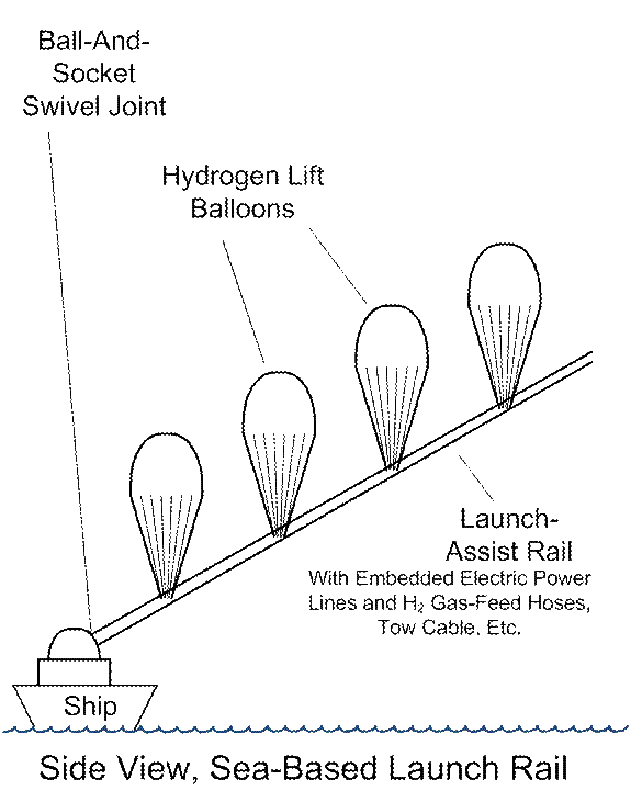
Figure
#16
Now the
side view does NOT show clearance for the rail-climbing vehicle(s), so here is
another drawing of only ONE section of doubled-up lifting balloons, from
rail-end view, on an inverted “T” shape supporting the rail, with the
envisioned rail-climbing assembly of vehicles, in this case, being an
air-breathing carrier jet with a rocket strapped on its back. Obviously, there could be many combinations
and permutations here, we could even have double rails to support a
double-fuselage carrier (base) vehicle…
Strain gauges (twist sensors) in the launch rail and / or level /
out-of-level sensors per lift segment (cross-members) could be used to pump the
hydrogen back and forth from one side to the other to maintain per-left-segment
balance.
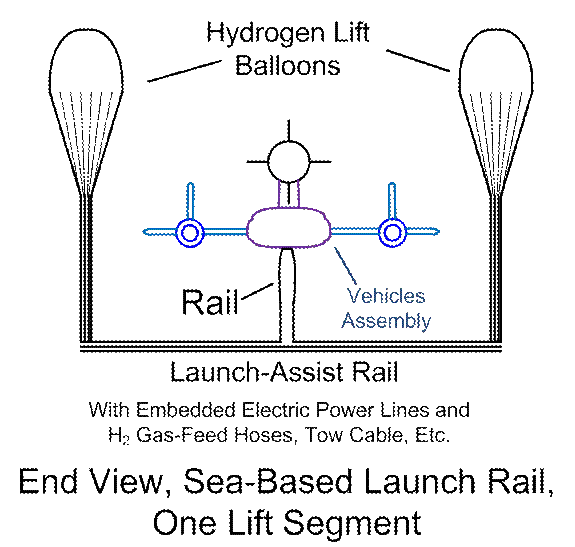
Figure
#17
We have
shown the side view of the sea-base (ship) end; probably it would be worth our
time to illustrate the top end of the launch rail as well… Here, a much larger set of balloons is needed
to suspend the power station, flywheel, motor, generator, and cable-pulling
pulley. This could be… who knows how
many tens of thousands of feet in the air?
The upper limits of hydrogen-balloons lifting powers are
mind-boggling… 24 miles high is not out
of range, see http://online.wsj.com/article/SB10000872396390443675404578056061642681072.html
, and that was with a helium balloon, which has less lifting power than a
hydrogen balloon. If we have the weight
of a rail and a power station to suspend, we can settle for less, but just to
show, the sky really IS the limit here!!!
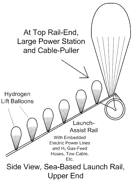
Figure
#18
As a
tiny bit of gory engineering detail, it might be worth it to mention this… If
the rail is very long, then the cable to be pulled will be very long, and so,
the cable-pulling pulley at the upper end would probably need to have an
internal motor to move the spool back and forth, to distribute the collected
cable evenly along a long spinning spool (and not let it chaotically jump back
and forth on top of a heap; I am assuming here that we don’t have a
super-strong, super-long cable or string, whose cable diameter is negligible; I
am assuming such things are still too futuristic; a long-long cable is
otherwise going to pile up WAY high in our collecting spool, unless the spool
has a long spin axis, a wide collection area, and can shimmy back and forth, in
a controlled manner).
OK, a
few more boring, gory engineering details…
The assembly of to-be-launched vehicles are going to be of substantial
weight. Do we REALLY have to build the
entire rail to be strong enough to resist BOWING as these vehicles pass
by? No, we do not! The first who-knows-how-many thousand feet of
rail, we could build to be fairly slight and weak… And we could suspend most of the weight of
the ascending vehicles with their own lift balloon(s). Slowly (20, 30 MPH at most, say) winch-style,
cable-pull it up, with a lift balloon or set of balloons, attached to the
ascending assembly, with the lift balloon(s) carrying most of the weight,
perhaps even assisting the lift. The
ascending vehicles could perhaps even periodically, totally stop during their
ascent. That could allow to tow cables
to be swapped out, distributing the masses of power stations (cable-pullers),
and could allow for periodic adjustments in the amount of hydrogen in the lift
balloon(s) attached to the ascending vehicles (trade hydrogen with the over-all
system’s balloons and hoses). Only when
the ascending vehicles assembly reaches the last 2,000 or 3,000 feet or so of
rail, only THEN to we “beef up” the strength of the rail, and power up the
final cable-pulling apparatus to boost the vehicles to high speed, for final
launch. Obviously, we’ll want to detach
the vehicle’s lift balloons first, of course, for this final “sprint”!
FLOAT
Your Launch Rail, Variation #2
Now if
we stop and think about things, we rapidly will conclude that building a
slanted launch rail 24 miles up into the sky is going to be preposterously
expensive. And so it would indeed
be! So then we think it over, and then
we say, OK, well, good idea on the slanted launch rail, and so forth, suspended
by hydrogen balloons and all, but, why don’t we put it out to sea, assemble it
at sea 2,000 or 3,000 feet long (whatever it takes to get the to-be-launched
assembly of vehicles travelling at a good clip before it leaves the tip of the
launch rail), and then we CUT IT LOOSE and let it freely float up to 24 miles
or so, first, and then let it launch our rocket? At that altitude, the air-breathing rocket
carrier makes no sense at all, any more, I will bet; let’s just call it a
rocket, at this point.
After
the rocket is launched, the weight of the assembly is going to drop a BUNCH,
and now the lifting capacity of the hydrogen balloons is going to want to take
us further up still, which of course, we don’t want. We want to bring the whole thing back down to
our ship, to fetch and launch the next load.
So how do we do that? First off,
we have a still-spinning cable-pulling pulley, plus residual energy in our
flywheel. We suck all this energy dry,
and we start drinking hydrogen out of our gas balloons, and compressing
it. I’m not sure about the math here, we
may even want to chill it down so far that we actually liquefy it, to REALLY
compress it (I don’t know the energy costs of doing that, and of vessel walls
thick enough to keep it super-cooled and insulated in an energy-efficient
manner, v/s the energy costs and weight costs of fairly-highly-pressurized
compressed-gas vessels). In any case, we
compress it to make it more dense, to save the hydrogen, we don’t want to just
vent it and waste it. Compressing it
will make our whole assembly of launch rail, power station, gas bags, etc., far
more dense, and we’ll sink back to sea level.
A few propellers here and there (which are good for “intelligent
structure control” anyway) will be enough to allow us to propel the launch rail
back to the ship. And, we can drink
hydrogen all the way along (burn it with ambient air) in internal combustion
engines and/or fuel cells, all the way along, as an energy source. Oh, and, as previously mentioned, solar
collectors can be integrated into gas-bag walls, if that makes sense
weight-wise and economics-wise.
As a
further, probably non-obvious point, we can supplement the lifting powers of
the assembly, in the hours right before launch (probably get a few more miles
of almost “free” lifting power, by supplementing the heat in the gas-bags. Make sure we launch in the day-time, with
full sunshine heating the gas-bags.
PLUS, have diffused lasers (we don’t want to punch holes in the bags!)
from ship-side, pour a little extra heat energy in, if the weather will permit
it, from bottom-side up. AND, from
top-side down, whether the weather is good or not, we can have orbiting
reflectors be reflecting some additional solar power down onto the airbags, heating
them from the topside as well. NOW we’re
“cooking with gas”!!! After a few hours
(at most) of this, we’d be able to launch from a ridiculously high altitude (I
am not at all sure of what those numbers would be, let’s just call them
ridiculously high, and leave it at that).
Well, I
don’t think that additional drawings are warranted at this time… Elevation, tendency to twist, and launch
inclination (angle of attack) of the launch rail, can all be controlled via
already-discussed methods (do not forget, we can pump hydrogen gas back and
forth between different bags). What else
is there to say? Email me please if this
is not all clear, I can do more drawings…
FLOAT
Your Launch Rail, Variation #3 (and
Let’s Kill Some Hurricanes While We’re At It!)
Now how
about we take the above free-floating launch rail, and we ramp back DOWN on its
ability to free-float, and to navigate for itself (via propellers), and mostly
(or entirely) remove its ability to compress and/or super-cool its
hydrogen. This reduces weight,
complexity, and costs. Instead, the
launch rail assembly will be equipped with 2 or 3 (perhaps more for redundancy,
I doubt that more than 3 would make much sense) “C”-shaped grappler-hooks that
can open and close, to hand-over-hand “climb” a ladder up into the sky.
The
“ladder into the sky” would rise up from the ship at sea (could be land-based
as well, but we really do like to be at sea, not just for being at the equator,
but for some more reasons that will become clear soon). The sides of the ladder will be
hydrogen-conducting hoses that can pump hydrogen up or down, as need be, plus
provide structural tensile strength (a rope or cable, to put it simply), plus
(almost definitely, but not absolutely required) conductors for electrical
power. Plus, perhaps, fibre-optic or
other data and control lines…
The
“rungs” on the ladder might be separated from each other by hundreds, or, more
likely, thousands of feet. They would be
hundreds of feet long; long enough to provide sufficient lifting power and
separating distance to prevent twisting wind forces from twisting the entire
ladder up into a hopeless snarl.
Propellers for “intelligent structure control” can help prevent twisting
(snarling) here also. They would be
either A) long continuous horizontal fairly-highly-pressurized single tubular
gas-bags, whose internal gas pressure provides structural strength, or B) a
long carbon-fiber-based, or other lightweight-materials-based, solid trusswork,
supported by a line of NON-pressurized gasbags.
I am betting that “B” is a far better bet, for modularity (prevent one
large leak from taking out a whole rung of the ladder), and because maintaining
a controlled pressure is difficult and/or expensive, in the face of weather and
temperature changes.
The launch
rail plus gas-bags climber assembly would have, dangling down from a cable, a
straight-line long rod, with 2 or three or more “C” shaped assemblies (think of
the snap rings in your three-ring binder assembly or book) that clasp the
cables-hoses-etc. sides of the ladder…
Gas-pressure or electro-magnet or otherwise equipped to open and close
(one clasp at a time of course) to pass over each rung of the ladder, while
still staying attached. Provisions could
also be made to periodically connect and disconnect to the gas hoses,
electrical power, and/or data connections, if need be (between climber and
ladder structure , that is, of course).
One of
the beauties of this whole scheme is that when the rocket-launching assembly
reaches the tippy-top of the ladder, and discharges its payload, then it can
simply pump its excess hydrogen gas back into the entire structure, and be done
with it, and descend back down the ladder.
If the ladder is very busy with ascending vehicles, it might still make
sense to equip the climber with SOME small amounts of compressors, ballast
tanks, propellers, etc., to still go ahead and cut it loose, and let it make
its own descent, after off-loading excess lifting gas.
Boring
engineering details time is here again!
The ascending rail assembly, and each rung of the ladder (individually
one by one, one rung at a time) are going to be pulled upwards by gas bags, and
“want to be in the same place at the same time”, inviting snaring, snarling,
abrasion, entanglement, and chaos and badness in general! How do we prevent that? Well, mounted off of the bottom of each of
the truss-work “rungs” being supported by gas-bags, we are going to need to
have 2, 3, or more swiveling propellers (actually sometimes propellers, at
other times wind-harvesters) anyway.
These are needed to fight ladder-twisting winds, for example. When gas-bags-bang-into-each-other-time
arrives, when the given rung and the ascending assembly start to want to fight
each other… The propellers pull the rung
away. Similarly, the ascending assembly
will have propellers mounted at its bottom also, and these will almost always
be pulling the ascending assembly out laterally away from the ladder, to
maintain separation distance.
Now the
NEXT “cool thing” that could be done with our gas-bag ladders, other than
launching rockets off of their tops, is that, after we get some practice with
the technologies involved, we could, during hurricane season, travel up into
hurricane-breeding swatches of ocean, seasonally. On the lee (down-wind) sides of our ladders,
we could un-furl out floating assemblies of large (light-built, of course)
wind-harvesting turbines. Do NOT go into
the middle of a full-force hurricane, of course, there is no reason to risk
smashing up our delicate toys!!! Stay
out on the periphery of budding storms, where the wind forces are
manageable. Pipe the resulting energy
back down ship-side via electric wires, most likely. Another more far-fetched option would be to
gather moisture from surrounding air (in semi-stormy air, this should not be
hard to do) and electrolyze it into hydrogen and oxygen on-site. I doubt that this is or will be very
practical. More likely, we’ll split
water into oxygen and hydrogen ship-side, down on the ocean-top. Bottle up (liquefy) the gasses and shuttle
them shore-side for the stored energy, and other uses…
So
there’s LOTS of seasonal free energy to harvest out there, obviously. If we had huge armadas of such
energy-harvesting ships, we might even be able to tap so much energy as to deflate
the hurricanes a bit, and lessen the damage that they do when they hit the
shore.
As an
engineering side-note, I do wonder about this…
If our ladders and wind-energy harvesting scheme is as large as it might
need to be, then we might need large anchors to keep the ships on-station, and
not pulled away by these same winds.
Large-enough anchors, and the long-long cables needed to drop them ALL
the way to the ocean floor, in some spots, might not be an optimally economic
solution. Large ocean-floor-dragged
anchors also damage the environment down there, and the “tree huggers”
(“benthic nematode huggers” in this case, or more plainly put, bottom-dwelling
worm huggers) are quite right to object, actually. Go ahead then! I’m one of them, I confess! Just CALL me a bottom-dwelling worm hugger,
then, it’s all true!!! So anyway… How about a “water anchor” or “submersible
umbrella anchor”? I don’t know if such a
thing, or similar, exists yet, or not, but if not, consider it to have been
conceptually invented right here and now!
In deep-deep waters, where a conventional anchor might not be such a
good choice, a small tugboat pulls out away from the “mother ship” (OK, no,
we’re not going to talk about space aliens, certainly not just yet, so
sorry!). The tug-boat pulls out
(unfurls, deploys) cable, chain, or rope, to include floats most likely, so
that the tow rope will have at least a moderately strong tendency to float, for
easy retrieval later. The tug-boat ALSO
tows a giant “water umbrella” complete with strong, heavy struts, and heavy,
water-proof canvas. The whole thing is
dense, and wants to sink. It is at the
“tip of the spear” pointing towards the towing tugboat. The very tip of the umbrella is deliberately
made extra heavy, to “want to sink” the most.
As the tug-boat pulls away, the umbrella sinks deeper and deeper (but
obviously never reaching the ocean floor, which is the major part of our
objective). When “on station”, the
tugboat has dropped it down, say, 1,000 feet, 2,000 feet at the most, depending
on just how large this thing is. The
tug-boat now deploys a large float to provide at least SOME stabilizing force
to the chain or cable that ties the submerged umbrella tip to the tugboat, and
stops pulling away from the mothership (the tugboat has been pulling it into
the face of the blowing winds, or wind-ward).
Now the
forces of the winds blowing the “mother ship” and energy-harvesting scheme pull
the submerged umbrella OPEN by pulling it in the opposite direction, opposed to
what the tugboat was doing. The winds
have to now drag ALL that water with the ship!
The winds might do that a bit, but so what? Close enough to stationary is good enough,
and we have saved a BUNCH of chain or cable.
We no longer scar the ocean floor.
At most, we drag some nutrient-richer, colder waters up towards the
surface waters, which is beneficial in 2 ways: A) the critters at sea like
those nutrients, and B) that cools down the surface waters, which is powering
our hurricane-brewing machine in the first place. After we are done energy-harvesting at one
location, and want to move the mother-ship, we detach the umbrella anchor-chain
(or cable) at the mothership end, towing it from tug-boat end again (collapsing
the umbrella). The tugboat pulls it up
and back to the mothership, which can keep on towing it if we are only moving a
fairly short distance, or pull it up deck-side for a longer journey.
Are we
into enough science-fictionish-like ideas yet?
No? Well, let’s keep on moving
along, then… To maintain these kinds of
structures, we’ll want to build floating robotic “tugboats of the air”. They’ll come in various sizes for various
purposes. They’ll consist of a lifting
gas-bag, with a dangling assortment of “stuff” (computer, power source,
compressor, compressed-gas ballast tank, propellers, etc.), at the base of the
gas-bag. Dangling down from THIS, there
will be several octopus-like or snake-like dangling cables with power and
control wires, and hydrogen hoses, with, at the tips of these hoses / cables /
wires, grapplers, manipulators, and hose-tips for sucking H2 gas
from giant airbags (or for off-loading gas FROM the robot gas-bag TO the larger
structural gas-bag). These cables /
hoses bottom-dangling tips will look a bit like a squeeze pipette with a large
squeeze bulb, except that the squeeze bulb will be a mesh-enclosed, swiveling
propeller that orients (points) and moves the solid tubular part of the
“pipette” so that the business end is where it needs to be. With several such dangling assemblies coming
off of the bottom of our gas-bag robot, the over-all assembly will resemble an
airborne jellyfish!
The
duties of our armada of airborne jellyfish-robots will be to scuttle around,
inspecting for gas leaks or other damage, conducting repairs, and moving special
hoses and pumps around, if need be, to deflate a badly-failing entire large
gas-bag, to steal it’s remaining gas and feed said gas to its more healthy
neighbors, and then to ferry away the entire spent gas-bag, and replace
it. The jellyfish might carry small (or
medium-sized) insect-like, gas-bag surface-crawling hordes of robots, that go
out and “sniff” for gas leaks, and repair the small ones (glue of some sort,
perhaps?). So the jellyfish carries the
hordes of insect-robots from large gas-bag to gas-bag, once every month or 2 or
three per inspected bag, gathers them back up, and travels on to the next
gas-bag to be inspected. The insects
might affectionately be known as “fleas”, and the gas-bag robot carriers might
be known as “fleabags”!
Contest
time is here! I have tried and tried to
come up with a cute acronym (or set of acronyms) to name the FLEAS and
FLEABAGS, or similar, to name these various robots, and I’ve come up dry, so
far, so sorry! But… If YOU can come up with a clever acronym or
two, I will publish them, and give you credit!
Say your name is “Johnny Cook”, for example, then, just perhaps, if my
ideas take flight, hundreds of years from now, people will still call them
“Johnny Cook FLEABAGS”, for example! I
can’t think of many better honors, can you?
Back to
boring engineering details: How do we
allow the fleabags to access the insides of the gas-bags to inject or withdraw
gas? And make it easy to do? OK, we all know about the high-pressure
relief / injector valves on your car tire, or the much tamer (lower-pressure)
valves on your pool floatee-toy, we could sure do something like that… OR, we could also make some over-lapping
fabric strips in the surface of our gas-bag, with embedded permanent magnets in
the fabric. “North” on both of the
overlapping flaps pointing to the outside, “South” pointing inwards towards the
center of the gas-bag. They (2 flaps)
mate to each other and hold… A bit of
non-out-gassing sticky stuff to improve the seal, and we are OK… Now the fleabag appendage comes by, with a
gas-sipping or gas-injecting tip at its business end, poised for insertion
between the flaps. The fleabag deploys
small mechanical grabbers to secure the edges of the outside flap, leaving only
the inside flap free to be de-mated. The
fleabag now applies a strong DC electromagnet, and powers it up, with a strong
over-powering “North” pointing inwards towards the center of the gas-bag,
pushing both flaps inwards… But only the
inner flap is free to move! The “needle”
is quickly inserted, and the DC electromagnet is powered back down, minimizing
gas leakage. Just pull the hollow needle
out when done. There you have it!
Need any
more pictures, all clear so far? Holler
any time, more pictures if need be, email me at RocketSlinger@SBCGlobal.net …
All
right then, one last dive into some more wild ideas, verging into the more
science-fiction-ish… So now we have
already assembled our armada of power-harvesting ships with their hydrogen
ladder-balloon assemblies, and we’re all out there on the
hurricane-power-sapping mission, and we (and our employers and stockholders)
are all getting fat, dumb, and happy, harvesting all of that free energy. As a side benefit, we are also sapping a bit
of power out of the hurricane-breeding area of the open waters. But we find…
And I do believe that this will be the case indeed… That we are “venting our gaseous intestinal
byproducts in the hurricane” if you will, totally wasting our time, basically,
as far as SIGNIFICANTLY tapping into the power of the hurricane, to protect the
folks back shore-side.
We have
to find a new source of funding, now, if we can… The shore-side stakes are, really and truly,
in the tens of billions of dollars! That
will pay for a LOT of ships, fuel, airbags, etc. … If we can tap into it… Yes, we could go try and get the government
involved, and make our money off of taxes…
But we’d probably go bankrupt doing all of the paper-work, if the
government doesn’t beat us to bankruptcy in the first place! Maybe we can get the insurance companies to
pay us instead, we’ll be saving them a TON of cash, if we can demonstrate
hurricane-killing powers. So let’s assume
we can get paid to do it, by hook or by crook, and now move off to describe
what we’d do if we wanted to focus primarily on hurricane-hilling, and
harvesting energy secondarily, instead of vice versa.
We would
first off shed the towed turbines (detach the towed wind-energy-harvesting,
elevated turbines; bring them back down ship-side). Why?
Because their presence drags our “ladder” to be way tilted away from the
source of the winds, and we want our “ladder” to resume its
more-fully-vertical, un-encumbered position.
We move our ships (10, 12, 15, 20 of them, who knows) to the heated sea
surface where the hurricane is moving towards, to where the hurricane’s next
energy “feeding grounds” are. Now we
take our next inspiration from the musk oxen way up north, or the plains
settlers of long ago, and “circle the wagons”, or “circle the musk oxen”,
whichever your favorite analogy might be.
We must defend against the hurricane, so, circle the musk oxen! Bet you never heard THAT call to arms before!
So the
ships form a circle, all with ladders way up into the sky. Armadas of giant robotic gas-bags (the
previously described “fleabags”) scurry up and down, erecting a giant ring of
airbags up topside, at the top tips of the ladders, to form and secure them into a ring. Who knows, perhaps do the same thing, a few
times along the vertical length of the tied-together assembly of ladders. AND, deploy (unfurl) long “drapes” of thin,
lightweight air-flow-resisting sheets, to tie the ladders together, to form a
giant chimney. Fleabags can scurry
about, securing one sheet’s edge to another.
It may not be all that air-tight, but close enough is good enough. Paint this all BLACK, so as to A) suck up
heat and heat the air column within our giant “chimney”, to help the air rise,
and B) cast a giant shadow on the surrounding ocean waters, to steal away the
hurricane’s energy source. The ships can
move at will, keeping the whole assembly at the optimal spot.
Now if
we are lucky, the “chimney effect”, AKA “Venturi effect”, see http://en.wikipedia.org/wiki/Venturi_effect
, will allow high-atmosphere winds at chimney-top to suck hot,
moisture-containing sea-top air all the way up the chimney, and steal the
hurricane’s thunder. To boot, we’ll be
adding water to the high atmosphere, making clouds up there, bouncing off the
sunshine, reducing global warming, and sending rains to the deserts. If our
chimney REALLY gets cranking, maybe we can even re-deploy our energy-harvesting
turbines up the middle of the updraft, and extract some free energy, too!
If the
chimney does NOT want to fire right up of its own accord, we can put energy
INTO the system to get (and keep?) it going.
We can A) deploy giant propellers in mid-chimney to shove air upwards,
or, I suspect more plausibly, B) Inflate giant hydrogen gas-bags (or clumps of
gas-bags) to fill the majority of the chimney at sea level, and let them ascend
one by one. They will pull air upwards
in the wake of their upward movement. At
chimney-top, they dump the majority of their lifting gas back into the
structure, and descend for re-cycling.
An air-moving “bucket brigade” of giant versions of our favorite
“fleabags”, if you will!
Need more
illustrations? Speak to me, at RocketSlinger@SBCGlobal.net …
What
further evolution might follow the first successful assembly of such a
hodge-podge, thrown-together-at-sea assembly of such “ladders”, plus a
glorified, blackened wrapping of “Saran Wrap”?
Well, fairly obviously it seems to me, if we can create a TEMPORARY
emergency hurricane-killing (or at least, hurricane-alleviating) measure at
sea, then we can take the lessons learned, and create a longer-term, more
durable version of it. Longer term, we’d
create an assembly of a ring of semi-airtight, sheet-flanked “ladders” plus
adjoining sheets of these semi-gas-proof sheets, all suspended mid-air by
hydrogen balloons and ferried about at sea by a ring of 6-12-20-whatever-many
ships, and we’d roam the world’s oceans.
Kill a few hurricanes here, harvest some wind energy there, move on to
water some deserts over other-there the day after that… Oh, and let’s not forget, when we’re bored,
park on the equator for a while, and launch some rockets to the moon, Mars, or
beyond!
Not to
get too political on y’all, but, how about stopping trying to decide just
exactly WHO are the good guys, and WHO are the bad guys, in all those foreign
lands (Iraq, Afghanistan, Syria, Stanstanstanistan, North Korea, Mars, Jupiter,
who knows after that), and let’s just STAY AT HOME and spend a few tens of
billions of dollars to BUILD SOME NICE TOYS instead, to help and make things
better for us all, and the planet, and the bunny rabbits? And the lions and tigers and bears, oh
my? Maybe we could, for instance, for a
few tens of billions of dollars, instead of trying to decide, just who ARE the
right foreigners to kill, anyway, we could build giant water pipes and water
pumps instead, and we could pump and store flood-stage Mississippi waters, and
dish it out to replenish the Ogallala aquifer,
see http://en.wikipedia.org/wiki/Ogallala_Aquifer
, and then after that, pump some more of it out to replenish the Colorado river
basin? Price tag, $12, maybe $15 billion… TOYS FOR THE ENGINEER, BUILDER BOYS, I say, and
to heck with too many weapons for too many wars!!! Our supercomputer hardware and software is
FAR more capable, these days, I suspect, of telling us where the heat and cold,
water, wind, ice, clouds, snow, etc., might best be re-distributed, than it
will EVER be, in anything approaching the near future, of telling us where to best
re-distribute the killing of humans.
Accordingly, even though we know there’s “a time and a place for
everything under Heaven” (yes, including war), let’s do some serious
down-funding of the killing toys, and some up-funding of the building toys,
really soon now. Not to denigrate the
services of the warriors; it is just that we should be asking a LOT less of
them! War is a hardly-ever-useful tool,
a blunt and ugly thing.
Sorry,
had to get my digs in, after all this time, and now that I have run out of
engineering ideas… I will stop now, and
not get too much further political; this is not intended to be that kind of web
site!
(To be continued… Only if and when I come up with more
ideas! Or y’all send me some! So sorry, folks, I am flat-plumb, OUT of
ideas now!).
07 April
2013 Update: MORE Wild Ideas (Mostly About Balloons)
Hi
y’all, I am back! Before we get to the
more serious near-term future stuff, I do have to confess, I had a wild
science-fiction idea the other day…
Literally and truly, actually, I had a night-time, dream-state, science
fiction dream, I do have those from time to time… This one told me that to REALLY get some
out-of-this-world propulsion, we have to step OUTSIDE of our travelling
vehicle, and even outside of ourselves, perhaps, and push on something else
“out there”… WAY “out there”, I guessed, when I pondered my dream afterwards. I scratched my head a while, and could only
conclude that when we “shove mass out of our ass end” for gaining propulsion,
maybe we’d better figure out how to grab so-called “dark matter” and shove THAT
aft-wards! As soon as anyone figures out
how to do that, then, I have hereby “defensively published” this idea, and so
the patent trolls may kiss my aft end!
OK, back
closer to the here and now… There have been recent advancements in the field of
“aerogels”, to include the manufacturing of lighter-than-air, aerogels, some of
which are based on the graphene form of carbon.
I am told that most if not all aerogels are made in a liquid solution,
and then the liquid is pulled out, being replaced by a gas. I assume the lighter-than-air aerogels must
contain hydrogen or helium, then, although I have not read specifically. Y’all are as capable of “Googling” as I am, and
so, I will throw a single link your way, here, and then we’ll move on. http://www.earthweek.com/2013/ew130329/ew130329c.html
...
So,
suffice it to say that aerogels are making progress, and can be VERY
lightweight; lighter than air, even, while retaining at least SOME small degree
of mechanical strength. And so that got
me to thinking… Making a safe and PRACTICAL
hydrogen balloon may NOT depend on making major chemical or nano-tech
advancements, above and beyond the state of the arts today! Here are the central ideas of what will be
elaborated on below: Create a fabric
that is layer upon layer upon layer of Mylar (or similar thin semi-gas-proof
material) and aerogel… Mylar-aerogel- Mylar-aerogel- Mylar-aerogel- Mylar-aerogel-over-and-over-again,
to a thickness of an inch to several inches.
Make a GIANT balloon out of this, because the cube-square law says that
the larger an object is, the lower is the ratio of surface area to volume (our
lifting power goes through the roof, overwhelming the weight of the heavy,
thick, multi-layer balloon surface, if the balloon is simply LARGE enough).
Now for
the next step: Make the balloon itself,
multi-walled. The outermost wall is an
inch or a few inches thick of this multi-layer fabric that I have described, to
make it more gas-proof. Then there are
spherically radially arranged internal “struts” that are mostly made of
aerogels, with a few internal strands of carbon fiber or fiberglass, or other
lightweight structural materials, that span from the outermost balloon skin,
running a few feet or yards in length, until they mate to the innermost balloon
skin. Both the innermost and the
outermost balloon skin are made of the multi-layered, VERY gas-proof material,
see, and they are secured to one another by these very lightweight (almost
definitely denser than air, though) structural “spacer” elements. These “spacers” help to enforce a giant “air
gap” between the innermost and outermost balloon skins.
Now for
the killer idea: The air gap should be
filled by PRESSURIZED NITROGEN! OK, so,
pressurized nitrogen is denser than air…
So!?! So we make our balloon WAY
huge enough to overcome this all. And
what does the pressurized nitrogen buy us?
It buys us a non-flammable encasement of the hydrogen to be contained
within the innermost balloon walls. SOME
of the pressurized nitrogen will leak out to the ambient air, and that is a
waste of money, but we can live with it.
SOME of the pressurized nitrogen will leak slowly into the internal
(neutrally pressurized) giant innermost hydrogen-filled gasbag (and that’s not
good, either; the hydrogen will slowly get polluted by nitrogen leakage, and
lifting power will be lost, and the whole bag will need refresh or maintenance
treatment). But, if the balloon walls
leakage rates can be made at least somewhat acceptable, the lifting power should
last a LONG time… AND the pressurized
nitrogen layer strictly ENFORCES that hydrogen can NOT leak directly into
ambient air, which is where the explosion (think Hindenburg) hazard comes from.
That is
the core essence of my idea here… Now
for just a few embellishments. On the
somewhat science-fictionish side, internal robots (“fleas”) could scurry around
inside and outside the bags, looking for, and fixing, leaks. A point or two or more, on the over-all
assembly, might allow tubes to bring hydrogen out to the ambient-air surface,
where hydrogen can be burned for energy harvesting. A string of such balloons could be strung up
vertically along cables and hoses to feed (fairly) pure nitrogen and hydrogen
upwards, along with electricity and control wires or fiber optics as
desired. The vertically suspended and
spaced balloons, of course, suspend the weight of the cables and hoses, to
reduce the need for super-strong cables.
Here is
an important idea: If the hydrogen that
feeds upwards to the next-higher balloon, comes, not directly off of the main
feeder hose from below, but rather, from the guts of the below balloon, then
the slow pollution of the hydrogen (through nitrogen leakage) of the below
balloon, will just be passed upwards (the purity of the hydrogen at the bottom
balloons will constantly be refreshed).
The very top-most balloon, then, yes, will be filled with hydrogen that
is not at all so pure any more. This
might present and upper-most limit to how high the balloon-stack can be
stacked. Alternately, the feed rate at
which new gasses must be fed to the super-assembly at the bottom, becomes
impractical and/or too expensive. And
yes, at the very top, we could burn off (waste) the nitrogen-polluted hydrogen,
or we could burn it and harness the energy.
Yes, it
is true… The hydrogen in this assembly
will ALL want to be forced, by gravity-induced ambient-air-pressure
differentials, to the top-most corners of where it can go. So, periodically throughout the
structure… Perhaps even within layers of
each lifting balloon, internally, if the balloons are large enough… There will need to be “lift-capture walls”
inside the hydrogen hoses. These will
need to be “smart”; ideally with provisions for system control. The bottom side of each of these “lift
capture walls” will be significantly higher-pressured than the top side
(because the ambient air is “squeezing” the lighter hydrogen). Only a controlled amount of hydrogen should
slowly be allowed to work its way up the structure. If NO such provisions (“lift-capture walls”)
were made at ALL in a structure as envisioned here, then ALL of the hydrogen
would be “pushing” upwards and outwards at the very top-most tip of the
structure, probably bursting it, and providing NO distributed lift throughout
the vertical span of the structure, if the whole structure is very tall at all.
PS, the
pressurized nitrogen outer layer of lift balloons as described here, can, to a
limited extent, countervail against the gas-bag-distorting tendencies of the
pressure differentials that are worrying me here. If the nitrogen pressure here was
ridiculously high (with the attendant mass problems), then yes, a large lift
balloon would NOT need to worry about these distorting forces. THAT whole can of worms (to build internal
“lift capture walls” inside the lift balloon, or not, or to crank up the
nitrogen pressure, or not, and, just HOW large are we going to BUILD these
balloons, in the first place; the latter being a WAY relevant factor), I am
going to have to leave to folks who are WAY smarter than I! Meanwhile, I have fended off the patent
trolls, you can thank me later… You can
yank me, you can crank me, you can thank me, just PLEASE don’t ever spank me
(even though I do know, I HAVE been a bad boy, especially in the eyes of the
patent trolls).
PPS,
pressurized nitrogen is an excellent choice here for yet ANOTHER reason, and
that is because nitrogen, unlike oxygen-containing gasses like air or other
gasses, will NOT suspend water, which is an enemy of lightweight aerogels as
they exist today, because aerogels wildly LUST after absorbing water &
other liquids, which bogs them down, makes them heavy…
And just
WHAT do we do with our vertical structure here?
As previously described here on these web pages, pretty much, except I
will want to list a few variations, and/or, more thoughts:
‘1) As described on the main page, www.rocketslinger.com
, we could build some tall towers with reaction-mass-injector JETS travelling
up the rails that support a methodology of launch-assisting a fairly
conventional rocket. What was NOT
mentioned there is this: We could
incorporate LIGHTER THAN AIR large assemblies (as just now described) to build
these towers out of…. Then the sky is
the limit! Or, your budget is… Why not an assembly of, say, 4 super-tall
towers, built out of balloons as described here, but with lightweight SOLID
cages around them? And stack the solid
cages that are balloon-filled? Unlike a
conventional sky-scraper, they do NOT all cumulatively add weight to the
bottom! Now equip the towers as
described on the main page, and off we go!
Launch-assist (defy the rule of “must burn the fuel to carry the fuel to
burn the fuel to carry the fuel…” with pre-positioned reaction mass) all the
way up to, what, 30,000 or 40,000 feet?
Why not? Or more practically, use
tow cables to pre-position the rocket for launch up at say 27,000 feet, and use
the assisted-launch, reaction-mass-injecting scheme only for the last 3,000
feet, say.
HOW
would such towers be constructed? Send
me an email at RocketSlinger@SBCGlobal.net
to say that this matters to you, and I will elaborate, and/or draw some
pictures…
‘2) Let us assume we do NOT build a rigid or
semi-rigid structure as assumed above, but go more so with the free-floating
assembly of vertical columns of balloons plus hoses and cables? What then?
“You can’t push on a rope” here means we can’t assume any kinds of
straight lines or straight launch rails that last for very long in their straightness… Use electrical energy (harvested off of winds
that blow by, and/or solar collectors on the surfaces of the structure, and/or
from electrical wires from land or sea below, and/or from tapping into the
energy from burning hydrogen as we steal a wee tad off of it as it is fed
upwards), and we can use this electrical energy to lift the payload to
launching position by either ‘A) Using electrical motors and conventional air
propellers, or ‘B) “Ionic Wind” propulsion as described, for example, in http://www.sciencedaily.com/releases/2013/04/130403122013.htm
.
‘3) Use a free-floating giant lifting balloon
that is toroid (doughnut) shaped, to allow the lifted rocket to sit suspended
down below the toroid, on a cable-suspended launch platform, so that the rocket
can be fired right up the MIDDLE of the giant air-bag doughnut, without
endangering the lift toroid. If the lift
toroid is large enough, this will work.
To descend back down, after shedding its load, the toroid assembly would
compress the thin air around it, to use to burn enough of its hydrogen to
create enough energy to compress enough of its other hydrogen load, to finally
be heavy enough to settle back down to the Earth, to gather it’s next
payload. Such an assembly could
free-float WAY high, and (optionally) could be gently, remotely heated (to
increase its lifting power) by lasers from the surface and/or from orbit. This is probably the most practical and
near-term affordable version of such things.
‘4) A
hollow launch tube is also possible, including a vacuum-filled launch tube,
with a “plasma window” at the top. See http://en.wikipedia.org/wiki/Plasma_window
for the “plasma window”, and yes, we are getting QUITE science-fictionish here,
if we are talking about using such things for launching spacecraft through a
vacuum-filled tube. If you want to see a
more closely related exposition about what I am envisioning here, please see http://en.wikipedia.org/wiki/StarTram
. They mention a “megastructure” to
build the vacuum tube to launch a rocket through, all the way to high, high in
the atmosphere, where we apparently envision energizing the “plasma window”
(VERY energy expensive if we can build it that large at all!) a few seconds
before we open the “mechanical gate”, and then the rocket goes through, and
then the mechanical gate once again shuts, and then the “plasma window” can
once again be de-energized… ALL in order
to preserve the vacuum in the launch tube!
Fine and
dandy, I say, but, they never really described the “megastructure” for
supporting this vacuum tube to go
high-high up into the atmosphere. If and
when we EVER get to this science-fictionish scenario, here is how I would build
that tube: Suspend each section of it up
in the air, surrounded by pressurized nitrogen, then neutral-pressurized
hydrogen, as previously described. With
a few additional details: Inside the
inner, larger, weight-lifting, segmented hydrogen balloons, there is yet
ANOTHER small layer of pressurized nitrogen, so that ANY leakage of pressurized
gas, into the launch tube, is of neutral nitrogen, not of explosion-supporting
oxygen or hydrogen. Then at the core, of
course, is the vacuum-filled launch tube.
And the whole vertical assembly of tube plus 3 layers of segmented
(segmented meaning, containing internal “lift capture walls”) is then “guy
wired” in 4 or more directions, by cables coupled to feed hoses to lift
balloons, so that the lift balloons lift themselves, AND lift and enable the
“guy wires” (cables) to resist wind forces, on the entire vertical structure,
no matter what the wind direction may be.
So… Pressurized nitrogen (thin
layer), hydrogen lift layer (thick layer, neutral pressure), then final or
innermost pressurized nitrogen layer,
then REALLY finally, the rigid-walled vacuum-filled launch tube. That’s what we’re looking at.
AND I
might add, the rigid-walled, final, innermost tube, that would be vacuum-filled
for final use, should have indentations (at 3 or 4 radially spaced intervals)
so that an internal “crawler” could crawly up its interior, to bring up
materials to build the next stage, as it is built, vertically. ONLY after it is finally assembled, THEN it
will be air-pumped out (vacuum-filled), for supporting launches. AND I might add, the “plasma window” is,
well, um, a non-essential “window dressing”, if you will. If we build this thing into the stratosphere,
if thin air rushes into the “mechanical gates” at the tip for a few seconds or
fractions of a second before the rocket merges, SO WHAT?!?!? We pump it out afterwards, again, and just
DEAL WITH the in-rushing impact of thin-thin air as we emerge, what, 30 or
40,000 feet in the air, if we do this right?
Need
pictures or more details? Happy to
oblige, just email me at RocketSlinger@SBCGlobal.net
, Have Windows Visio, Will Travel… For the
right price! I can BEST be bribed by MANY-MANY
bottles of frozen Jagermeister, I might add…
OK, I
guess I’m about done for today… Except
for one last thing! I want to add that
***IF*** my ideas are used, to include the (stolen from “Wiki”) ideas of the
“plasma window”, then, (further if-else clause), ***IF*** the electromagnetic
forces associated with the “plasma windows” upon the human (or non-human)
occupants (or their descendants) of a thus-ejected-from-the-tube spacecraft
should enjoy BENEFICIAL biological, mental, spiritual, genetic, or epigenetic
effects of such-induced electromagnetic, social, electromagic, or Feng Shui
effects of said forces, then I hereby convey these benefits to the public via
“defensive publishing” (patent trolls, suck wind!). IF on the other hand, said “plasma window”
causes the implosion of the Universe as We Know It, then… I had NOTHING to do with it, I KNOW NOTHING, “Wiki”
is to be blamed for ALL of it!!!
Yours
Truly, RocketSlinger
Back to
main page… www.rocketslinger.com