From (by) RocketSlinger@SBCGlobal.net (email me there please)…
This is a sub-site to main site at www.rocketslinger.com …
This web page last updated
21 Aug 2026
Practical,
Low-Costs Methods for High-“G”-Forces-Tolerant Cargo Deliveries to the Moon
Abstract
This sub-page to www.ResearchGate.net (at https://www.researchgate.net/publication/413440844_Practical_Low-Costs_Methods_for_High-G-Forces-_Tolerant_Cargo_Deliveries_to_the_Moon
) is duplicated at www.rocketslinger.com also (at http://www.rocketslinger.com/Low_Costs_Hi_G/ ). This is purely creative “brainstorming”, speculation,
and internet research here. No hardware
was constructed, tested, or even simulated.
Previous pages (mostly by the same author) are linked to discuss details
about custom-built “impact runways” on the moon, for receiving fuel-saving
high-velocity “crash landings” of high-G-forces-tolerant cargo. A new focus here is on sandbags (often quite
large sandbags) filled with lunar regolith, sometimes arranged in a “V” shape,
with the tip or downstream part of the “V” omitted, to create a funnel, on the
Moon’s surface, for catching and guiding the incoming cargo vessel (spherical
in this case). After the incoming cargo
accepts path guidance from the “V” shape, the cargo exits the “V” shape, and
plows through one or more spaced berms of regolith, placed perpendicular to the
cargo’s path. Another version of cargo
craft is bullet-shaped, which is described but rejected for reasons listed. Other options are discussed, such as topping
off these berms (also possibly the “V” walls as well) with over-shooting partly-horizontally-oriented
augmented sandbags for containing “upwards-splatter”. This option may be impractical for costs
reasons.
Other topics addressed are
solar-powered (or more likely nuclear-powered) Earth-to-the-Moon-and-back
shuttles that would be ion-propelled “slow boats to China” for ferrying
no-huge-hurry bulk cargo from the Earth to the Moon, and (for example) Moon
rocks and regolith for research back to Earth.
A (likely pneumatic-piston-driven) method is described for
simultaneously separating the ferry-shuttle from the cargo, at each end of the
journey, while decreasing the cargo velocity and providing a velocity
“kick-back” to the ferry-shuttle, for the return trip.
Contents
Preamble, and Bits of
Boilerplate. 2
More-Specific Introduction, and Previous Papers Overviews. 3
Finding Sites for Moon-Surface Impact Zones. 16
Sandbags and Sandbag-Containing Walls. 18
Shooting Down the Bullet-Shaped Cargo Vessel 25
Using a Spherical “Cannon Ball” Instead.. 26
Guiding and Propelling the Cargo Vessel Flights. 29
A Macro View of the Crash-Landing Walls. 31
Shooting Down the Cannon-Balls… Literally This Time! 32
Concluding Remarks. 34
References. 34
Appendix, Chats With AIs Log.. 35
As before, as with other
sub-pages of www.rocketslinger.com , and the mirrored
content at ResearchGate, part of the intent here is to “defensively publish”
miscellaneous ideas, to make them available to everyone “for free” (sometimes
called “throwing it into the public domain”), and to prevent “patent trolling”
of (mostly) simple, basic ideas.
Accordingly, currently-highly-implausible or speculative design ideas
(frequently marked as such) are sometimes included, just in case they ever
become plausible, sometimes through radical new technology developments (often
in materials sciences domains).
Dear Reader,
excuse me as I will often slip out of the prevalent stilted formal modes of
writing here. I have no boss, bosses, or
style-guides to please with these “hobby” writings of mine, so I’ll do it my
way! I’ll often use a more informal style from here on in,
using “I”, “we”, “you”, etc. “We” is you
and me. “You” are an engineer, manager,
or other party interested in what’s described here. Let’s thwart the patent trolls, and get ON
with it!
PS, if some of my speculations are
wrong (based on mistaken assumptions), please email me at RocketSlinger@SBCGlobal.net, and note that I’m open
to co-authoring articles, even if they are short, as in, corrections or updates
to this article, for example. If you
send comments, please specify whether or not you’re open to having your name
mentioned (up to and including being named as a co-author) in any follow-up
article(s) or commentary.
I’ve written several previous papers on this topic,
since this is a bit of an (autistic or at least mildly autistic?) obsession of
mine, and because I think that the possibilities here are rich (possibly very
rewarding) and currently undervalued.
Let us now review them, in reverse (newest to the top) chronological
order, and (when appropriate) criticize them in retrospect of them being
published.
See https://www.researchgate.net/publication/380783853_Artemis_Accords_Proposed_Coverage_for_Lunar_Impact_Cargo_Deliveries (mirrored at http://www.rocketslinger.com/RIFFLE/ ) for my most recent
paper. This is common-sense
recommendations for amending (or supplementing) the Artemis Accords concerning
this topic. The earliest phases of such
Moon-impact projects for cargo delivery might simply be an open, un-improved
range, except for incoming terminal guidance for incoming, steered cargo, which
might include retro-reflector mirror arrays, laser, radio, or microwave or
maser beacons, and even large 2-D-printed bar codes, cell-phone-style. Such a barely-improved impact range might be
called a “RIFFLE” Range, for Regolith
Impacting Fuel-Frugal Lunar Expanse (or Ellipse,
take your pick).
At the end of this paper,
I mention yet another idea for an improved impact range, or decelerator. This would be a long path of inverted
half-pipes, with the open sides facing downwards. Timed to meet an incoming cargo-projectile,
held-captive pneumatic plungers would shoot upwards into the half-pipes, loads
of regolith. To increase “dwell time”
for the regolith to stay up there and impede the cargo, some unspecified
additive might be added to the regolith, to turn it into “moon slime” (AKA
“goop”) that slowly drips back downwards.
Weaknesses here are
many… The half-pipes would presumably be
made of (at least partially) “in situ” resources (regolith), AKA lunarcrete, but would still be expensive, in the needed
quantities. Cargo-path guidance would
need to be prohibitively accurate, or the first opening of the half-pipes would
need to be large, at the very least.
Shots-timing of the (doubtlessly expensive) pneumatic “shooters” (which
would recapture and recycle the compressed gasses, in a held-captive-at-the-“gun
point” end of the cylinder and plunger) would need to be very precise. Said “shooters” would be eroded (at the inner
diameters of the tube-walls) rapidly by the sharp micro-edges of the being-shot-out
lunar regolith, even with the preventative measures described in the
paper. The additives needed to make
“moon slime” (for increased dwell time) are unknown, and-or perhaps wildly
speculative. And the half-pipes would
need to be suspended up above the lunar surface, costing yet more structural
materials.
https://www.researchgate.net/publication/360935871_High-G-Force_Impact-Landings_Methods_of_Cargo_Delivery_to_the_Moon_Spinning-Barrel-Style (mirrored at http://www.rocketslinger.com/Hi_G_Cargo_B/ ) is fairly short, and
describes spinning the cargo in the same style as the British did in World War
II; see details about the British “bounce bomb” that we’re cribbing off of,
here, see https://en.wikipedia.org/wiki/Bouncing_bomb and https://www.sciencefocus.com/science/how-did-the-bouncing-bomb-work/ and
(best or most detailed) https://www.ukessays.com/essays/physics/physics-dambusters-bouncing-bomb-9609.php . For our application here, I envision a
“Moon-orbiting mothership” (or ships plural for opposing prograde and
retro-grade orbits, for reasons described in the paper) imparting the spin onto
the cargo-barrels for Moon impact. This
could be done to decrease the linear travel distance on the Moon, of the
spinning barrel. The HUGE problem here, is
that this would impart spin to the mothership, which (if the cargo size is
large enough to be practical) is so large that the mothership would have a HUGE
problem in cancelling it’s
own (imparted upon it) spin. Although
some methods are listed in the paper, I think that they are impractical, to say
the least.
https://www.researchgate.net/publication/338534654_High-G-Force_Impact-Landings_Methods_of_Cargo_Delivery_to_Earth's_Moon_or_Other_Heavenly_Bodies_Lacking_an_Atmosphere (mirrored at http://www.rocketslinger.com/Hi_G_Cargo/ ) is a quite-long paper
with detailed (long but simple, mostly algebra and not further advanced math)
to “show the math”. It considers what
kinds of cargo would be appropriate, incoming velocities at Moon impact, and
deceleration “runway lengths” v/s incoming impact speeds, and (magnitudes of)
“G” forces to be pulled during deceleration.
The latter parts of the paper describe what would have to happen if we
would try to make such Moon-surface-mounted deceleration device compatible with
humans and other living cargo. Such
ideas are highly speculative, and MIGHT work, only with large advances in
science and technology, especially (possibly) in the materials sciences domains. But the ideas are listed anyway… In the interest of fending off the “patent
trolls”! This is the one paper that I
will repeat segments from (or refer to) the most, in further discussions
below. It’s worth at least a casual read
or skim-read.
In retrospect, I would
criticize this paper for referring entirely too much, to the use of large
amounts of (expensive) moon-crete or lunarcrete, and other expensive engineered modifications of
the lunar surface. We absolutely MUST
pay attention to costs and practicality, as I will attempt to do now, in this
new paper.
https://www.researchgate.net/publication/335218915_Ping_Pong_Mass_Momentum_and_Kinetic_Energy_Exchange_as_a_Method_of_Spacecraft_Propulsion (mirrored at http://www.rocketslinger.com/Ping_Pong_ME/ ) describes some WILDLY
impractical ideas (for now, with today’s technologies). But I am all over the opportunities to fend
off future “patent trolls”, every chance that I get, and as I frequently repeat! The “ping
pong propulsion” idea will be recycled here, in a much milder or simpler
version.
The relevance of this
paper to Moon impact landings is that parts of it are closely related. This paper here mentions clouds of Moon dust
thrown high above the Moon, to impede the velocity of an incoming
spacecraft. This would require tightly
controlled timing, and other complexities.
The energy costs, technology, and capital costs would most likely be
prohibitive. Also mentioned are the
following: “ME bouncers” (Mass Exchange
bouncers), which are launched (by electromagnetic rail guns) from the surface
of the Moon, directly into the path of the incoming spacecraft. There, the ME bouncers will hit the craft’s
protective shell (shield), bounce off, then return to the Moon’s surface for
refurbishment and re-use. This is
likewise highly impractical, for similar reasons. Also, the collisions would be at
impractically high speeds, causing much damage to both the incoming cargo
vessel and the bouncers. If we are going
to damage (often shatter) the cargo craft, we should do it on the Moon’s
surface, where the scattered materials to be collected, won’t be scattered as
widely. Rail guns are large, require a
lot of maintenance, and are expensive, by the way. My previous paper http://www.rocketslinger.com/Hi_G_Cargo/ fleshes out more details
about launching clouds of Moon dust, and variations on this “tech”. Use “Appleton
silo filler” as a search string in that paper to find these additional details.
Another introductory
remark here is that I have (for the first time in writing these papers) often used
AI (my favorite, used almost
always is “Perplexity”). I wrote this
paper; AI did not. I’ll try to recall to mention which items mostly come from AI (“Perplexity”),
so that you (Dear Reader) can help me to double-check such items, if you are so
inclined. In my experience, AI has made
massive strides recently in reliability, so why not use it?
Introductory remarks here,
I think, should cover WHAT impact speeds are we talking about? From my previous paper http://www.rocketslinger.com/Hi_G_Cargo/ , for reference, see https://www.mpoweruk.com/Apollo_Moon_Shot.htm , where we see that 5,600 MPH was the
incoming speed (in the Apollo program) of a spacecraft from Earth, in a “free
return” orbit, without yet having burned the fuel required to perform “orbital
insertion” into moon orbit. This will
serve as our approximation of a good “high velocity” impact-landing. From the same source: After an orbital insertion burn for orbiting
the moon at a low but stable altitude (of 69 miles), the orbital speed was
3,600 MPH. Also for (comparison)
reference, the speed of a gun-bullet
is about 2,500 feet / second. That’s
about 1,705 mph. So we can see that we
are almost always (excluding a lot of fuel burned to soften the landing)
talking about speeds MUCH faster than a speeding bullet!
As an exercise to the
reader, look up slow-motion videos of bullets ripping through various
targets. Intuitively, this serves as a
check on some of my not-well-thought-out ideas, as well as some of the ideas of
others. See M.A.C.E.D.O.N.A.S. —
Momentum Absorption Catcher for Express Deliveries On
Non-Atmospheric Somata, developed by Charalampos (Charis) Kosmas / Lunar Cargo. About the same thing, see also ESA OSIP — Low Cost Lunar Cargoes OPLONAS
& MACEDONAS , Space.com — “An entrepreneur wants to build a
giant net to catch spacecraft landing on the moon” , (It describes MACEDONAS
as essentially “a butterfly net on
bungee cords”: the catcher intercepts the incoming package, and an attached
decelerator slows it down until it reaches the landing pad), and Universe Today —
“Building A Giant Catcher's Mitt On The Moon” , and MACEDONAS concept video — Charis
Kosmas . OK then, also https://contest.techbriefs.com/2021/entries/aerospace-and-defense/11340-0702-001817-lunar-cargoes-oplonas-macedonas . I don’t have the math or physics details for
you, but I intuitively believe that inertia in a target that is hit at
multiples of the velocity of a speeding bullet, would
be torn to shreds, before it could absorb much impact energy. Let’s see a demo in a lab on Earth!
Introductory remarks here,
I think, should also cover WHAT is to be impact-cargo-delivered. What kinds of cargo are
hi-“G” resistant? Google it, or ask an
AI. Or also from my previous paper http://www.rocketslinger.com/Hi_G_Cargo/ , for reference, see the
following imports: One consideration is,
what magnitude of “G” forces are we going to target, and what kinds of cargo
can be selected or designed, that will withstand such forces? Consulting https://en.wikipedia.org/wiki/G-force , we now duplicate a few
entries from their table, just for general illustration and for brief
discussion:
Space Shuttle, maximum during launch
and reentry 3 g
Maximum g-force in Tor missile system[28] 30 g
Space gun with a barrel
length of 1 km and a muzzle velocity of 6 km/s, as
proposed by https://en.wikipedia.org/wiki/Quicklaunch (assuming constant
acceleration) . . . . . . . . . . . . .
. . . . . . .
1,800 g
Shock capability of mechanical wrist watches[30][31] > 5,000 g
Rating of electronics built into military artillery shells[34] 15,500 g
OK then, what about the
actual materials most needed on the Moon, that are
suitable for “cargo crashes”? Carbon is
high on the list; there not being much carbon on the Moon. Here is a recycled list (from the same
previous paper) of choices of forms of carbon, that could be sent from the
Earth: Candidates then are graphite
(pure or near-pure carbon), charcoal (50% to 95% carbon, see http://www.fao.org/3/x5328e/x5328e0b.htm , typically around 70% to
80% carbon at the center of the distribution-shape bell curve), coal-charcoal
or coal-“coke” (see https://en.wikipedia.org/wiki/Coke_(fuel), about 85% carbon for
good-grade or steel-grade coke), petroleum coke (see https://en.wikipedia.org/wiki/Petroleum_coke, about 98.0% to 99.5%
carbon for the pure grades), or anthracite coal (see
https://geology.com/rocks/coal.shtml, about over 87% carbon). Non-perishable foods (think dried beans and
dried grains, for examples) could also be shipped this way. This was also discussed in the above paper,
and in the appended discussions that I’ve had with the “Perplexity” AI. The AI and I have also chatted about granular
fertilizers for Moon agriculture. So I
won’t go into more details right here, about carbon and food-stocks. I don’t want the main body of this paper to
get to be too long and boring.
Carbon and foodstuffs
(etc., and granular cargo) should be well protected from impact, in “capsules”,
as described in the previous paper. I’ve
not drilled down into details about this yet, and so will do that now. These capsules should NOT be large! Maybe a foot or 2 (3 feet at the most; AKA a
meter at most) long, for example.
Why? Because of
pressures and wall thicknesses of vessels or containers in general. I searched the internet for a simple, cogent
explanation of this, and couldn’t find one.
So I made my own. See Figure #1
in https://www.researchgate.net/publication/365964188_Propulsion_Designs_Using_Novel_Nested_COPVs_and_the , AKA mirrored at http://www.rocketslinger.com/COPVs/ ,which will now become Figure #1
here. See the just-now-linked document
to get a more detailed explanation, and note that internal pressures alone, aren’t much different from internal and external
pressures combined, for our purposes here, in the impact scenario. Thus the need for smaller
containers. In simple terms,
stresses and strains around the circumference of a cylinder or sphere add up
with larger circumferences, and so larger vessels (and pipes, hoses, etc.)
require thicker walls to restrain said additive forces.
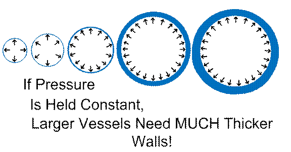
Figure #1
My best guess for an
optimal material for these capsules for granular and other special cargoes
needing extra protection would be low-carbon or plain carbon steel (from my
chats with AI). This metal would be easy
to recycle on the Moon. Moon colonists
would have little need, I suspect, for many of these capsules, so recycle them! On the other hand, extra-precious cargos
might need tool steel capsules. Planning
for a variety of standardized capsule sizes might be wise.
Now we need to add a new
drawing to make sure that the reader will follow what I mean by a threaded
capsule with large hex-heads protruding from the ends, for strongly fastening
them together and then pulling them apart, with large wrenches.
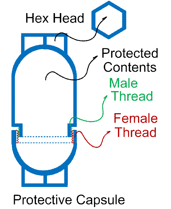
Figure #2
There would be wasted
space inside the female-threaded end as shown above, unless one leaves a small
fill-hole that is welded shut or otherwise secured (like a much smaller
threaded hole at the base of the hex-head at the female-threaded end of the
capsule, or through the middle of the hex head) after filling and screwing the
parts together. I suppose I should have
inverted the entire drawing above to make it more intuitive, but invert it in
your mind’s eye, as you fill it on Earth.
You fill the male-threaded end of the capsule completely full, and pack
(tamp) it in. The large opening is very
nice to have. One could even fill it
with large chunks of carbon (coal for example) with the voids in between filled
with powdered graphite, or other carbon powder.
Now screw on the female end of the capsule, leaving the fairly large
void. Here we go,
the best idea here is, leave a small hole clear through the hex head on that
female-threaded capsule-end, with a small male-threaded mating part. Fill the remaining void through this small
hole-in-the-hex-head (don’t let them tell you that we do NOT need a hole in our
head!), plug it, and we are done! The
topper-offer small hole being located in the thick, bulked-up area of the hex
head (making the threaded small fill hole longer) also is best for not
compromising on structural strength of the overall capsule. This might be obvious, but let me add that
the small-fill-hole threaded male part should be recessed, not poking out,
after final assembly, so that it won’t be broken and knocked off. Also, this male-threaded plug should have a
hex indent for a hex driver, or other type of “screwdriver”-like device, for
use on the Earth end. Pulling this plug
on the Moon end will most likely be used, also, for preventing spillage, unless
the Moon people want to open up the capsules over a giant bowl, to catch
spillage after opening up the main threads, if the contents are “topped off”.
Obvious variations could
be made as desired to the above, which should at least get the general idea
across. Let me prominently mention this,
though: These protective capsules could
also carry not-too-highly-toxic-or-dangerous liquids. Nitroglycerin is excluded! So are highly radioactive materials. For carrying liquids, gaskets (seals) at the
main threads may need to be added. The
male-threaded small fill-hole plug could be replaced by an emergency
pressure-relief outlet, similar to what is used on pressure cookers. Top-off operations should be mostly or
entirely omitted, to leave spare room for air, an inert gas, or partial vacuum,
to accommodate expansions of the liquid contents. In transit, in space, an Apollo-era-style
spacecraft “rotisserie roll” could be used to moderate temperatures. And liquid cargoes (just like food-stock
cargoes) should be rapidly recovered at the Moon end, post-impact, to avoid
temperature extremes. Candidate liquids
include water, most especially, but also perhaps methanol, ethanol, various
petroleum liquids, oils, lubricants, surfactants, paints, varnishes, and so
on. Clear contents-labelling will
obviously be vitally essential!
For extra protection on
extra-precious cargo, one could even add (COPV-style) heat-cured epoxy and
carbon fibers around the threads, to be cut or ground (via grinding) away at
the Moon-destination end. Painted colors
and-or RFID tags could be added for labelling the contents. Or engraving might work, too. Note that nothing but metals will do here (I
strongly suspect), and that metal detectors will work well when “fishing” these
(metal!) containers out of the regolith and sandbags after impact. After this “tech” is tested and thoroughly
validated, without significant losses of transported materials, even fairly
precious metals might be carried by these protective capsules.
What-all kinds of metals
do we want to crash-land on the Moon, to supply our Moon colonies for
industrialization? I am no expert, so I
chatted with AI about that. See the
appended log of AI chats for details, but AI “Perplexity” tells me to be
careful to not provide too many different kinds of alloys, which can be
confused with one another, which can impede recycling when undesirable types of
metals are combined (the same thing is true of plastics as well as
metals). Semi-finished metals “stock”
will be discussed shortly.
Well, let me just quote
the AI here. I’m not educated enough on
these matters to argue about this.
“If I had to minimize the number of imported metallic material
streams for an early equatorial industrial site, I would choose:
- Low-carbon steel / iron.
- A 6xxx-type aluminum alloy.
- An Al–Si casting and welding alloy.
- Copper.
- Nickel–chromium alloy additions, including selected stainless
feedstock.
- Ferromanganese and small reserves of Mo/W/V tool materials.
- Tin in protected small inventory.
- Titanium alloy as finished high-performance components, not bulk
metal.
- Carbon/graphite as a protected strategic consumable, even though
it is not a metal.”
End quote. (More AI-provided details are added in the
appended chats. And asking an AI for
more information is easy.) For
semi-finished metal stock, most of which should be able to withstand high-“G”
crash landings, if oriented and packed (protected) well enough, we might have sheet
metal, bars, pipes, tubes, rods, wires, insulated wires, and more. Finished high-“G”-resistant products like
certain tools and tungsten-carbide and-or diamond-studded drill bits and saw
blades, for example, should be packaged as finished products, not as
constituent metal “root stocks”, obviously. Later on, I will write about
spherical v/s bullet-shaped cargo vessels.
For “long” semi-finished metal stock, we’ll prefer the bullet-shaped
vessel, as will be discussed. Such stock
includes sheet metal, bars, pipes, tubes, and rods. If they are bent or mildly damaged upon
impact-delivery, sometimes they’ll be able to be fixed. Or cut away and use the less-damaged
subsections and remelt the rest!
Dear Reader, not to insult
your intelligence, but to state for clarity:
Yes, aluminum and iron are available as ores on the Moon. Titanium too. But gathering the ores and refining them into
useable metals is a HUGE hassle! We’ll
want to take it easy on our colonists, and help them through their early days! The same thing goes for supplying them with
impact-resistant food stocks and fertilizers as they try to get Moon
agriculture established, of course.
Now (for more about
metals) I will import a drawing from http://www.rocketslinger.com/Hi_G_Cargo/ , for reference, and
discuss it here.
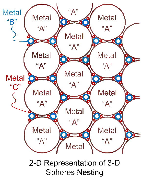
Figure #3
In the earlier paper, I
discussed filling the final voids between the smallest spheres with a carbon-based glue, such that the carbon in the glue might
be recycled (along with other glue ingredients?) where large chunks of
balls-plus-glue can be fished out of the wreckage. Gluing them all together might help protect
other cargo, as impact energy is absorbed in tearing apart the assembly (of
glue plus balls). Scattered spheres
might serve as “ball bearing” like devices or lubricants to “ease the forward
travels” of other cargo (between the cargo and the Moon and-or sandbags full of
regolith, for example), instead of having too many too-sharp impacts damage
said cargo. Is the glue a good or a bad
idea? I’m not sure. I am just brain-storming here.
Parenthetically, let me
add that the “Figure #3” above is also “Figure #3” in http://www.rocketslinger.com/Hi_G_Cargo/ , so use “Figure #3” as a
search-string there, if you want to review my earlier thoughts about the
matter.
With or without glue, we
can tightly pack many different kinds of metal cargo into different sizes and
types of spheres or mostly-spherical shapes, and then fish them out of the
wreckage. These spheres would all be
intended to be molten down, as an alternative to semi-finished or finished
metal stock or parts. It’s just an
idea… It would still beat gathering and
refining raw ores!
The spheres could be
intermixed with the protective capsules as shown in Figure #2. Once again, I don’t know if that’s a good or
a bad idea. For future references to
this idea, in discussions below, I will refer to these collections of different
mixed kinds of “round things” as “M&MMs”, for Metals & More
Metals. Now and then I like to use
“cutesy” or memorable names, to help them stick to the reader’s mind. As I think about it more, M&MMs may be of
limited use. If we do everything right,
“wreckage” shouldn’t happen too often.
Still, perhaps M&MMs could be used for “filler” around unique,
strange-shaped objects when packaging materials into a cargo craft.
While we’re writing about
metals, let me mention that the AI pointed this out to me, when I mentioned
axially-crushable hexagons as energy-absorbing structures for packing cargo into
the impacting vessels: The use of
aluminum for such crushable hexagonal “honeycomb” structures,
is already well studied. AI gave me https://ntrs.nasa.gov/api/citations/19690011603/downloads/19690011603.pdf as a reference link for
that. See also http://heroicrelics.org/info/lm/landing-gear-strut-honeycomb.html and https://www.sciencedirect.com/science/article/pii/S0094576520307487 . This fits in well as a protective packaging
material for us, obviously to be packed with cargo on Earth. Crushed aluminum can be recycled on the Moon,
of course, as could the intact honeycombs (that survive) as well. Or said intact honeycombs could find other
uses on the Moon, one of which might be in the construction of cargo
deceleration devices (such as inside sandbags), but this is an option that
doesn’t appeal to me much, so I don’t intend to discuss it further. I think that already-refined aluminum is too
precious to use on the Moon, where regolith will do! Enough said?
If, after cargo impact,
crashed, crushed, and shattered aluminum honeycombs are turned into not much
more than aluminum powder, with the metal powder so badly intermixed with
regolith, that extracting the aluminum (without significant impurities remaining)
is highly troublesome, we have another option:
Incorporate the aluminum dust plus regolith impurities into a structural
material of blended regolith and aluminum!
See E. J. Faierson, K. V. Logan, B. K. Stewart & M. P. Hunt
(2010), “Demonstration of concept for fabrication of lunar physical assets
utilizing lunar regolith simulant and a geothermite
reaction,” Acta Astronautica,
67, 38–45. … Also see Lopez
et al., “Friction stir additive manufacturing of
regolith metal matrix composite” (2024).
(These are from AI and I haven’t double-checked this in any kind of
detail.) Such aluminum-regolith blends
could surely be used on the Moon, but burning fuel to get them up to Moon
orbit, for adding them to cargo vessels (for impact) would make no sense, that
I can see. Such blended materials might
possibly find marginal uses in Moon-surface “deceleration devices” as described
here, though. That last statement will
also apply to the metal to be described below.
Molten salt (or molten regolith)
electrolysis can split lunar oxides (regolith) into oxygen gas at the anode and
a reduced metal/alloy mix at the cathode.
Dear Reader is left to himself or herself to go find the references or
papers. The resulting metal alloy will
be brittle and unpredictable, just like the above-described aluminum-regolith
blend. Both of these materials can
probably find better uses than in our “deceleration devices” described here, so
they are only of passing interest, here.
For me at least.
I’ve written at some short length about this (site-finding)
at http://www.rocketslinger.com/RIFFLE/ . There, a “box canyon” was described as being
ideal. I have also discussed this with
an AI (see the appended chats). Upon
further consideration, I no longer consider it highly desirable for an “impact
range” to be located in a valley or “box canyon”. With good guidance, an incoming impact-cargo
vessel (coupled with small-to-moderate-sized rockets and-or cold-gas thrusters)
should be able be able to confidently hit a target within a “3 sigma” limit of
about a 40 meter radius (my summary of an AI answer). Couple that with the “deceleration devices”
as described here, and we’d be able to set this up in
the flattest real estate that we can find, for our convenience. An important caveat is that we should, at a
large distance (maybe 5 or 10 kilometers, maybe more) away, have a large, tall
mountain or crater wall to catch errant “shots on goal” that might, for whatever
reason, miss the target on the high side.
We need a down-range backstop for safety, that is. We’ll be “shooting” at our target at a very
low angle, or tangent to the Moon’s surface, has been implicit all along here,
by the way. Maybe 1, 2, or 3 degrees at
most, away from, purely tangential…
I could be wrong. Perhaps it might be best to find a “box
canyon”, or at least a valley, to catch “splatter”, and errant shots to the
sides. I’m not prone to arguing much
about such things. Insisting on a valley
or box canyon will restrict our site choices, though.
Site choices depend on
whether our “shots on goal” come from a prograde or retrograde Moon orbit,
especially if we get picky about exactly what kind of site we want. High-“G” impact traffic doesn’t care much
about pro-grade v/s retrograde, but soft-landings traffic much prefers prograde
orbits. This is because the Moon’s spin
is slow, and linear motion of the Moon’s surface due to spin is a small fraction
of a hypervelocity impact’s speed.
However, said spin is a more significant factor when performing a soft
landing; you want the spin to help, not hinder, you in this case. For safety and traffic control we should
simplify, and settle on prograde orbits only.
This also helps when co-manifesting (or “convoying”) soft-landing and
crash-landing spacecraft.
Energy efficiency (low
“delta V” from Earth) demands that our impact range be equatorially located, on
the Moon. Eventually, our impact range
might also want to “catch” captured and guided (propelled) metallic asteroids
as well. Most of these asteroids will
come from the “plane of the ecliptic”, so there,
again, we want to be at the equator. And
we’ll want to be co-located fairly closely with an energy-hungry industrial
zone. Capturing bountiful solar energy
is easier at the equator (with flat solar collectors on the ground, not raised
high up on towers on ridges, like at the poles)… At least, during the lunar day! Most industry will run during the day, I bet,
with nuclear power being too troublesome and expensive, in large amounts, to
sustain heavy industry during the lunar night.
(This will hopefully change some sunny day soon, with the advent of
practical fusion power.)
The best real estate at
the poles will be scarce and precious, and an impact range (for safety) will be
real-estate-hungry. For this reason (and
considering international politics), a polar impact range (while possible)
should be ruled out. Moon-manufactured
goods will need to be traded with the pole or poles (for polar water for
example) via Moon roads, railroads, and Moon-suborbital rocket-propelled
“hops”, I suppose.
The only other
consideration that I can think of is that any location close to lunar caves
should be avoided. Lunar caves, just
like polar regions, will be precious real estate! Moon quakes induced by an impact range
(especially if it evolves towards using larger cargo vessels) just possibly
might endanger caves, and any people living in them, eventually. Unless the cave geology (Moonology?) can be
thoroughly investigated and validated as being Moonquake-proof, and-or the
cave(s) and internal habitats there can be “beefed up” in a near-bulletproof
manner, any impact ranges should be located far away from caves.
I can’t think of a more practical and affordable
method of stopping our speeding cargo vessels than regolith-filled
sandbags. Making sandbags out of “in
situ” gathered regolith is possible, see https://www.esa.int/gsp/ACT/projects/moon_fibres/ . My
off-hand opinion is that using such fibers may not be practical and affordable
in the short run, for the large quantity of sandbags that we’d need. As time and budgets permit, experiments on
the Moon, with this, is what I’d recommend, with the first sandbags brought in
from Earth.
What kinds of materials should such sandbags be made of? Kevlar, perhaps, or Vectran. Let experts (more well versed than I)
decide! Perhaps even
woven dense plastics. See https://www.lpi.usra.edu/meetings/lpsc2007/pdf/1380.pdf for the latter.
There’s lots of links out there for regolith sandbags in general, so
Dear Reader can go find it for themselves. Or wade through my appended chats with AI.
AI kept on mentioning one aspect of lunar sandbags,
that being retaining the “fines”, or fine-grained lunar regolith. Why should we care if we lose these, and are
left with only the courser stuff?
Under-filling the bags is better than having them totally “taut” full
(for preventing bursting) anyway. See https://ntrs.nasa.gov/api/citations/20080000853/downloads/20080000853.pdf for that.
AI never explained this, but I was disregarding that (retaining the
“fines”) aspect, till I thought, wait a minute, if repeated mechanical shocks
(as we will plainly see in our application) drive these “fines” (with their
very sharp edges) into the sandbag fabric (Vectran or
Kevlar for example) itself, then these tiny shards will cut into, and degrade,
the sandbag material. So an inner liner
of some fairly simple, cheap protective plastic may be in order, for containing
these “fines”.
Another special additive for our purposes might be
to add an inner layer of radar-reflective “tinfoil” (aluminum foil) if we
decide to put radar into the avionics of the cargo vessel, so that it can “see”
(and target) the structures of sandbags.
Other than that, I am skeptical of adding many layers of different
fabrics, for costs considerations Research “inflatable habitats” by the
likes of Sierra Space, for example, to see what I mean. We don’t want our sandbags to be that fancy
or expensive! But note that if they can
securely fasten metal (for doors for humans etc.) then we can do the same, for
sandbags… Stitch, sew, rivet, clamp, or
otherwise secure cables or other stiffeners to our sandbags, as needed.
With fabrics now having
been addressed, let’s discuss what the bags should look like. The smaller ones should be about the same
sizes as on Earth, ranging up to a bit larger.
They should have stiffeners (sometimes metallic) and handles. Handles may be metallic (cables for example)
or stitched-in loops of materials, and these handles should be liberally
arranged around the surfaces of the bags, for easy handling. Astronauts will wear clumsy gloves, and most
robots won’t be optimally both strong and dexterous, like humans on Earth, so
plan accordingly (for the closing mechanism as well as providing many
handles). These many handles are needed
for handling not only entire filled sandbags, but for handling damaged ones as
well, for recycling them into newer “over-bags”. Bare metal handles (loops) would also be
useful if one wants to mate the bags (damaged or undamaged) to “lunarcrete” as well, since fabrics won’t bind well to
concrete. The bags should come in
various sizes and lengths.
Ripped and torn bags, with
their contents partially or entirely spilled, can be recycled by stuffing them
into “over-bags”, which should be slightly larger than what is stuffed into
them. Over-bags should also have a
slippery inside surface, to facilitate this recycling. The outside surfaces of the bags need to be rough, or high-friction, to prevent slumping and sliding in
your sandbags wall(s). Note also that
over-bags full of smaller bags and fragments of bags (filled with alternating
bags, or fragments of cut-up bags if need be, and regolith) will also impede
the loss of regolith (spillage) out of the over-bags. That is, when recycling small scraps,
alternate layers of recycled scrap fabric and regolith should be used, for
optimal anti-spillage effects.
Sandbags and robotic
sandbag handlers should be co-designed to at least some extent. Yes, the Moon’s gravity is only 1/6th
that of Earth, so the bags and their regolith will weigh less there. Still, there is an upper limit to the size of
filled bags that can be easily lifted and moved around. Super-large and super-powerful robots will be
super-expensive!
Before moving on, let me
at least briefly describe a possibility…
Probably an expensive and (at least in the short term)
impractical possibility, but a possibility nevertheless. I call them “ugly snowflakes”. Regolith can be fused together (or partially
fused together) using heat from lasers, microwaves, masers, electrical heating
coils, solar power, or “other”. Suppose
we pour regolith down a shielded, manufactured void, in the presence of the Moon’s
gravity of course, and heat the regolith fine powders. The shields are there to protect our heating
elements from electrostatically attracted “Moon dust”, and need to periodically
be cleaned. If heater elements are used,
perhaps we need a “refractory coating” (think “kiln wash” for pottery and cermaics kilns on Earth) in there, as well.
I like the idea of using
lasers and masers. New masers (microwave
lasers) might fit in here; see https://phys.org/news/2026-08-semiconductor-maser-room-temperature.html . Continuously powered lasers and masers may be
energy-hogs. So shoot them through a
thin but long line of falling, fine Moon-dust, with the falling line of dust
being long enough to absorb all of the energy (and not get wasted heating up
the far end of the apparatus). PULSE the
lasers and-or masers in synchrony with the local falling-rate in the Moon’s
gravity. This will concentrate the
applied power to localized regions of the falling dust.
Filter out the largest resulting
sintered or semi-sintered void-filled particles, AKA “ugly snowflakes”, and
recycle the rest, through the apparatus once again. The results may be added to regular regolith
to “soften” the contents of sandbags.
This may be too expensive, and every time that the “ugly snowflakes” are
strongly mechanically impacted, many of them will collapse back down to dust. They would be energy-absorbing sacrificial
materials. But I thought that I should
at least mention the idea. Such an idea
might be used elsewhere, to create thermal or radiation insulation superior to
simple regolith. Think “Whipple shields”
(look it up).
So how do we use our
sandbags, to make impact-energy-absorbing walls, or cargo-vessel-deflecting
walls, to steer the vessels to the energy-absorbing walls? Having longer and shorter sandbags at hand
should be helpful, as shown below. We
could have one sandbag wall backed up by a ramped berm of regolith, or two such
sandbag walls “sandwiching” regolith in between them. I’m not sure which is better. I suspect that a simple regolith berm (minus
the sandbags altogether) would provide too much of a sloped surface, which would
deflect the cargo vessel too sharply upwards, away from the Moon’s surface.
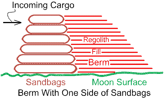
Figure #4
The above drawing shows
(intuitively) the value of having on hand, multiple lengths of sandbags. The sandbag wall (left edge) is shown as
slightly tilted, to resist toppling over.
This will deflect our cargo vessel upwards, which isn’t good, but we
have to make engineering (design) compromises.
The above assumes that the filled sandbags won’t be too heavy to move
around and arrange properly. From a
front view, they will be flattened, and should be arranged in “courses”, as
bricks or concrete blocks are laid in courses also.
Another alternative is to
have TWO such sandbag walls, with loose regolith in between the two. I’m not sure which choice is better, for
building costs or for maintenance costs.
I am noting the probably-obvious here, but the sloped berm on the right,
above, is shown conceptually-only. The
real bare (no sandbags) slope to the rightmost edge of the drawing is show too
steeply, for my convenience in drawing it.
Also it might be flat-topped, before sloping down to the right, for
depth, and for forming a road on the top, for maintenance access.
Much larger sandbags could
be used if we give up on being able to move them after filling them. These would need to be filled using 1, 2, or
more fill-holes on their tops. No covers
or caps on the fill-holes would be needed.
At the front, for lack of a better term, a more-open “fill lip” could be
used to drop smaller bags into the impact-facing end of the large sandbag. By using “compartmentalization” on this end
of the large sandbag, the smaller sandbags would impede the out-flow (spillage)
of regolith when the large sandbag is breached.
As usual, many attachment points should be placed around the tops of
these large sandbags. These will be
needed by robots (attached to cranes or otherwise) for holding open the
fill-holes and fill-lips while the large sandbags are filled. Also, when the impact-facing ends of the
large sandbags are damaged badly, the resulting voids in the wall can be filled
by “dangling” appropriately-sized and shaped (often large) regolith-filled “sand
pouches”. These “sand pouches” will be
attached by ropes and cables, to the existing (damaged) wall, but they will
need attachment points. Thus we have
several needs for liberally festooning these large bags with handles or loops
all around, on their tops, front and rear alike.
The fill operations (for
large sandbags and sometimes for the dangling repair pouches as well) can be
done by robotic cranes, equipped with a “bottom-discharge skip” for dumping
regolith. See https://www.boscaroitalia.com/cp/concrete-buckets/ for examples as are used
by Earthlings today!
OK, now for a drawing of a
large sandbag, which perhaps can be regarded as a hybrid
between a sandbag, and an above-ground flexible-walled vinyl pool, on Earth.
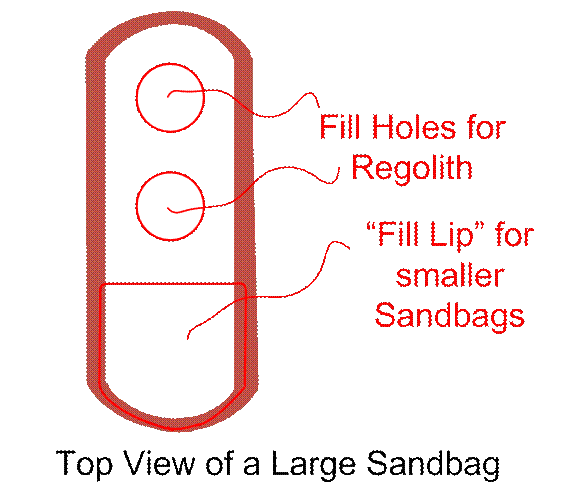
Figure #5
Suit yourself, but I am
thinking that the above width might be 2 to 4 meters and the height might be 1
or 1.5 meters or so. LARGE! The length can be arbitrary; maybe 8 meters or
so. They can be stacked together
lengthwise, or, of course, backed by a loose-regolith berm. From the front, they should be arranged in
“courses”, as before, with smaller bags.
There are two (2) circular regolith fill holes, but there could be more. The fill holes will be filled, forming conical
piles. We COULD bother to stir these
piles around (to settle them), with, for example, a “vibrator tool” with a
sealed rotating gear with an offset mass, but I wouldn’t bother. No one knows much (yet) about regolith
settling behavior, in piles like this, but (as was previously remarked) loose
filling, not over-tight filling, is desired on these sandbags, anyway. In use, shock and vibrations will settle
these piles soon enough!
Not to insult the reader’s
intelligence, but the bottoms of these large sandbags will be uniform, without
holes or other embellishments… Think of
a vinyl-fabric backyard above-ground pool, which this vaguely resembles. As I said, we want a hybrid between such a
pool, and a large sandbag, in this case.
With these monstrously
large sandbags, I think that toppling over, or slumping, unlike with the wall
of smaller sandbags shown to the left of figure #4, shouldn’t be much of an
issue. Walls built of these large
sandbags should be able to present a near-vertical face to the incoming cargo
vessel.
I had an idea that I think
is too costly and impractical, but I will briefly describe it anyway. I am concerned about “upward splatter” if a
cargo vessel meets a shattering conclusion at the wall, and I am also concerned
about said vessel barely grazing the top of the wall, and bouncing
upwards. How about we take a look at
figure #4, and imagine an I-beam with its “foot” weighed down by small sandbags
on the Moon’s surface at bottom right, and tilted (supported by the berm and
sandbag wall) upwards at about a 45 degree angle? Now the I-beams can over-shoot the sandbag
wall, catching upwards “splatter” and providing more vertical reach, to stop
the cargo vessel. I-beams are precious,
so we could protect them with dangling small sandbags, I suppose. To give them a cute, memorable name, let’s
call them “Paul Bunyan’s toothpicks”. I
also considered the use of “reactive armor” to protect the I-beams, but AI shot
me down on that (for perfectly good reasons I do believe.) Sad to say, I think that the “Paul Bunyan’s
toothpicks” would be too expensive and impractical, on the Moon. But they are hereby mentioned…
I have a cheaper, more
practical alternative to “Paul Bunyan’s toothpicks” which won’t work for
catching upwards splatter, but will at least extend our wall-reach skywards. That is to top off our wall (small-sandbags
front wall plus flat berm behind it, or large-sandbags wall with a flattened
over-topping of regolith) with a slightly set-back plain unsupported sandbag
wall, as is shown in figure 4, to the left.
It will topple at any time that it is hit or grazed by a cargo vessel,
but it will extend our reach. This is a
tame version of “terracing” our wall. Or
we could go for all-out terraces, if we want to spend the effort and other
resources.
If sandbags-walls are
going to go unused for a long time (months or years perhaps), it might be wise
to cover them with specially formulated tarps, to help to prevent them from
degrading in the harsh lunar environment.
Kevlar or Vectran tarps covered with
riveted-on, overlapping (reptile-scales-like) aluminum “scales”, for example,
might do the trick. That’s pretty
tangential, here, so I’ll discuss it no further.
That’s it for sandbags and
walls… Let’s move on…
In a previous paper (see http://www.rocketslinger.com/Hi_G_Cargo/ ) I considered 2 basic
shapes for a cargo vessel, those being spherical (a “cannon ball” to be
detailed some more here, below), and a bullet shape (a blunt conical front end
and a cylindrical rear). I will now
metaphorically “shoot down the bullet shape” with more detailed thoughts and
facts that I have gathered (with the assistance of AI in this case).
This bullet shape lends
itself to internally, appropriately located “crush protection” in the form of,
for example, axially oriented aluminum honeycomb material, and cargos
consisting of a lot of also-axially-oriented “long stock”, such as sheet metal,
rods, bars, tubes, and pipes. The
problems become, how do we avoid “fishtailing” (or worse yet, tumbling) of the
bullet-shape? And the
associated side-loads? To avoid
all of this, we have to hit a consistently-constituted, or uniform barrier
(crush barrier, energy-absorber), at a near-perfect (perpendicular) angle. And the near-perfect barrier has to ideally
be large enough to span “3 sigma” or more of targeting radius (targeting
error). The barrier, thus, must be
oriented near-vertically, with all of the associated material supports
costs. All done AFFORDABLY!!! I am CHEAP!
I want our lunar colonists to survive in a low-budget era! Lunar “in situ” crushables
and structural materials for all of this sound prohibitive to me (especially in
view of them having to be repaired or replaced after every sacrificial
use). Further, if the incoming cargo
“bullet shape” goes and “clips (or grazes) the edges” of our barrier, it will
immediately tumble. A barrier of
sandbags would have to be uniformly flat-surfaced, front and rear (which would
be subjected to toppling over), to avoid differential forces and impact-induced
tumbling, as well. So I am, for now,
“shooting down the bullet shape”, unless new technologies or ideas can make
this idea far more practical.
In my discussions with my
favorite AI (“Perplexity”), I didn’t ask for this, but the AI re-wrote my above
statement as below. This is imported
just for grins and-or clarity, below, and for the Dear Reader to see an example
of AI writing v/s human writing:
“A bullet-shaped, axially
cushioned vessel has strong packaging advantages for long stock, but it creates
an operational dependence on controlled attitude, near-normal impact, and a
large uniform arresting target. A spherical cargo vessel relaxes those guidance
and barrier-uniformity requirements at the cost of losing a preferred crush
axis. Therefore, the spherical concept should employ radially symmetric,
segmented packaging and crush capability rather than a single axial honeycomb
system. Bulk liquids should not be relied upon as the primary shock absorber;
if used, they should be high-viscosity, low-volatility, compartmentalized
load-sharing fillers.”
Some of the above refers
to using hydraulic fluids for shock-proofing or packaging the contents of a
spherical cargo vessel or “cannon ball”, which I will now discuss below.
The “cannon ball” makes a
lot more sense to me, now. It will
bounce around chaotically, but makes our building of walls and berms a lot
easier. See figure #2 far above, and modify
it in your mind’s eyes. (I can provide
more drawings if I must; email me at RocketSlinger@SBCGlobal.net if clarification is
really needed). Modify the drawing (of a
protective capsule) by making it spherical instead. Delete the large threads (they would be hard
to form and hard to turn together and pull apart, and there’s cumulative
dimensional “creep” to consider as well).
For threads, substitute flat faces and forced mating. Adding a large gasket there is probably wise,
between the near-symmetrical sphere-halves.
For fastening them together, we thicken the walls inside the sphere, at
(say) 8 or 10 locations around the perimeter, with indents (external carve-outs
for clearance) for large bolts. Both the
sphere and the bolts would likely best be made of tool steel, despite tool
steel being hard to recycle.
One half of the sphere
should have indents (inside the indents!) to capture a bolt-head, perhaps
hexagonally shaped. Now the bolt won’t spin. On the other half of the sphere, we place the
washers and nuts. Now we do NOT have one
giant thread, but many smaller threads, to make it easier to pull this all back
apart, at the Moon end of things.
Inside the sphere, we pack
the cargo, of course. If the sphere is
large enough, it can accommodate previously-mentioned “long stock”. Substituting a “capsule shape” for the
spherical shape, for the over-all, top-level cargo vessel, is also an option,
for “long stock”, but will be likely to aggravate “side loads” on the impacting
processes. When possible, smaller pipes
should slide inside of larger pipes, and rods can fit
in there, too. Gathering and repeating
previously-mentioned ideas, we can pack in “M&MMs” in strangely-shaped
voids, and the most precious cargos inside protective capsules can have the
capsules protected inside conforming metal containers (think eggs and egg
cartons).
Remaining voids could be
filled with hydraulic fluids for more protection. I discussed this with an AI. It might be best to dismiss the idea
(usually) of recycling spilled fluids if and when we have a “bad landing”. Maybe bake the contaminated regolith to
recover constituent volatile compounds at the most, when convenient. Keeping that in mind, per the AI, top
candidates for packing hydraulic fluids might be high-viscosity mineral oil, polybutene/polyisobutylene, and
PAO (Polyalphaolefin is a synthetic hydrocarbon
lubricant). Other “hydraulic fluids”
could be used in small amounts, for specialized packaging needs.
At the Earth end, our
sphere should have small threaded holes (with threaded inserts) as was
discussed (but not diagrammed) for figure #2 far above. They (the 2 of them, on opposite
shell-halves) should be located at the thickened-walls areas close to the
bolt-holes. They should oppose one
another, so that one can serve as a fill-hole, and the other as the purge-end,
for the hydraulic fluids. Heat the
fluids (plus the whole assembly?) for lower viscosity as needed. Suspend the entire assembled “cannon ball”
plus contents, over a large “containment bowl”, and fill up the voids till the
fluids come dripping through on the far side (bottom). AI says that we should pack the fluids in
small little sealed cells. I think that that
would be too expensive and troublesome, so I recommend just using plain
fluids. Reverse the procedure on the
Moon, in a controlled, Earthling-friendly environment (again with a large
containment bowl). Add air pressure on
the high-side threaded small hole, and “blow out” the fluids (at the bottom) till
most of them are drained out.
I asked a silly question
about what packing fluids would be best to pack empty sandbags with. AI (in my opinion) correctly responded that
such cargo would be best folded tightly and mechanically compressed, with NO
packing fluids. Thinking about it, I
suspect that certain classes of cargo (fabrics to include, not just empty
sandbags, but also other fabrics etc., such as clothes, bedsheets, shower
curtains, plastic bags, printing paper, and other household goods) could be
shipped in special, non-fluid-filled vessels.
Tightly folded and-or compressed fabrics could even be used to “package”
(protect, separate) “misc.” metal household (and laboratory) goods such as
bowls, pots, and pans, from one another.
Experimentation here will tell the tale!
Perhaps even some very sturdy ceramic and glass household (and
laboratory) goods might survive, if properly packed.
“Cannon-ball” vessels
could also be used to bring in asteroids for study and for use on the Moon, in
a protected fashion. A near-moon
Lagrange point would be a likely place to “park” asteroids, for studies (and
possibly extraction of useful materials) there.
Some science (and manipulations of the asteroids) might be easier to
conduct in zero gravity, and some might best be done in a gravity field. After an asteroid is studied (and samples are
kept) at a Lagrange point, or in Moon orbit, sections of the asteroids that are
of special interest for study, only when they are still mechanically intact,
could be specially housed in protective capsules, and shoved (along with
unprotected chunks of asteroids) into a “cannon ball” shell. Protective (“packing”) materials (including
fluids) might be expensive to transport (and hard to use, in the case of
liquids) in zero gravity, so voids could be left there, and “sloshing and
smashing around” inside the vessel, on impact on the Moon, could simply be
accepted.
On the Moon, samples
archives could be kept for future studies, just as museums and universities,
etc., keep samples of fossils, ice cores, and drilled rock cores. Of course, studies can be done on the Moon
(some samples will doubtlessly be transferred to Earth). Other materials will be extracted on the
Moon. Metallic asteroids will be of
great materials value, as will carbonaceous chondrites. Rubble piles and stony
asteroids? Perhaps
not quite as much…
The cargo vessel (as
discussed about) will most likely be a sphere, or (with some compromises) a capsule
(with rounded ends), or a bullet shape (least likely pending future
advancements). In any case, a cargo
vessel would likely need to be liberally festooned on the outside, with
sacrificial elements (lost on impact) that are needed for power, guidance, and
propulsion. Any elements that are useful
on the Moon, and can be placed inside the protective shell, could go inside the
shell. When doing so, one would have to
be careful to make sure that the entry/exit points in the shell (for electrical
cables, fiber-optic lines, and MAYBE even fuel lines, and perhaps located
between the two half-shells) are suitably protected. They shouldn’t weaken the shell, and they
shouldn’t allow fluids (if any are used) to escape from the shell, in
significant quantities, on impact.
Let’s go down the list of
candidates that can NOT go inside the shell, and work towards those that are
possibly best located inside the shell.
Solar collectors and antennas (for communications and perhaps on-board radar)
clearly must go outside, as must most or all of propulsion systems (rockets and
cold-gas thrusters, and possibly ion thrusters as well). If a push-rod (or rods) from a ferry
mothership (discussed further below) needs to meet a “cup” (or cups) on the
cargo vessel, the “cup(s)” need(s) to go outside of the shell, of course. Avionics and power circuit boards, including
batteries (and perhaps even fuel cells), could be useful on the Moon, and could
sensibly be located inside the shell.
Avionics circuit boards on the Moon could be used for their computing
power, or to guide sub-orbital rocket “hops” to move materials around on the
Moon’s surface.
Let’s now discuss a “ferry
service” mothership that will travel in loops back and forth from low Earth
orbit to Moon orbits, back and forth.
Re-load and refuel in Earth orbit, and couple
up, there, with Moon-impacting loaded cargo vessels. If there’s no hurry-factor on the cargo, the fuel-frugal
“slow boat to China” approach could be used, with ion propulsion slowly but
surely getting the spacecraft from the Earth’s gravity domain to the Moon’s
gravity domain, and then spiraling down to a low Moon orbit, again slowly. (Look it up if you’ve not heard of it; use “low-thrust
spiral transfer” as a
suggested search term). Power for such a
ferry vessel would best be nuclear, if we are going to use the
”push rod” idea (see immediately below).
The push rod’s mechanical forces may be too sharp to allow the use of
large, flimsy, delicate, far-strung-out solar collectors (hence the
recommendation for nuclear power).
The “push rod” idea is
only vaguely related to forceful mechanical separation between rocket stages,
as rockets travel up out of Earth’s gravity field. I am looking for a longer stroke, with more
power. Compressed mechanical springs might
work, as would small explosives (or rail guns, etc.), but I favor a large
pneumatic tube, with the push-rod end held captive. After the push rod is used, air (or other
more-inert gasses, such as nitrogen or carbon dioxide) would be pumped out of
the extended chamber (and the rod needs retracted), back into a compression
tank, for future re-use. For control of
just exactly how much “push energy” is expended, sensors could track the speed
of the being-extended rod, and small sub-compartments of compressed gas could
be expanded (or not), as needed, for fine speed control. Actually, that is for speed
AND for spin control, see below.
One single push rod (and
receiving “cup” on the cargo-craft end) would seriously risk the separation
operation going off-balance, adding unwanted spin to the cargo craft, and-or a
wrong path. So three
or four (or even more) optimally-arranged push rods and cups should be used. The cups should be equipped with clasps
(clamps) to release or not release the rod-tips as is needed. If anything goes wrong during the “push
operation”, the clamps could refuse to open, and the aborted operation could be
re-loaded and retried. I hope that’s
clear. If not, as usual, I can provide
more drawings. Email me at RocketSlinger@SBCGlobal.net if needed.
The purposes of all this? Getting a bit of a “free
ride”. From a low prograde Moon
orbit, the mated ferry plus cargo ship separates forcibly, pushing the cargo
craft backwards, to a lower orbit towards crashing on the Moon. The ferry gets a forward push, helping it to
a higher Moon orbit, and along its way back to Earth. In a still-sort-of-low Moon orbit, the ferry
craft can meet other craft from the Moon’s surface, loading it up for materials
to be returned to Earth.
What kinds of materials
might return to the Earth? Helium 3,
perhaps (look it up). Rocks, minerals,
and regolith (the REAL McCoy, not simulations!) can be returned to Earth, for
studies and for engineering purposes. So
can aged materials, such as sandbag fabrics, for engineering studies,
also. We need to know which materials
are most durable on the Moon’s surface, and why.
What some readers might
not know is that lunar materials can be used to manufacture a heat shield “in situ”. See https://ntrs.nasa.gov/citations/20130013482 = “Regolith Derived Heat Shield for Planetary
Body Entry and Descent System with In Situ Fabrication” Coupled with drogue and regular main
parachutes, this (heat shield) could be used with our Moon cargo “kicked
backwards” in Earth orbit. Or we could
settle for ONLY the drogue parachutes, or NO parachutes at ALL (depending on
the exact nature of the cargo), as further savings.
A V-shaped formation of
walls on the Moon’s surface will guide the “cannon-balls” to the funnel-tip at
the “V”. The balls (vessels) will
hopefully-usually exit at the tip of the “V”, and then cross (penetrate) 1 or
more berms or walls in order to be brought to a halt. A bird’s-eye view is provided below. Heavier lines mean thicker walls and-or
taller walls, to focus probabilistically on where-all the vessels are most likely
to hit and travel (that may or may not be a good suggestion, but here it is.) Separation distances will likely be much
larger, but I am showing it for my drawing convenience.
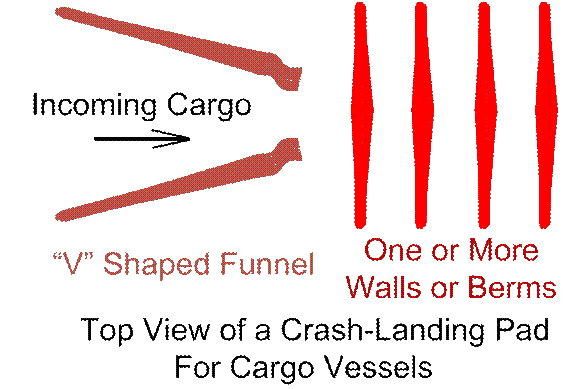
Figure #6
Spacing should be larger
than shown. Several “stopping walls”
(the vertical ones shown on the right above), rather than one super-thick one,
should be used, to make it easier to “dig out” a cargo vessel that is stuck
half-way through a wall. More spacing
means more time and distance for the heat of impact to dissipate, but that
effect is rather small, at these high speeds.
More importantly, a totally buried vessel will radiate away heat more
slowly than a partially buried (partially exposed) one.
High-speed cameras should
be deployed and active during cargo strikes, to be used for studying the impact
processes, and for making engineering improvements.
The cargo vessel should
“shoot high” at the targeted crash-landing pad, so that final adjustments on
close approach can mostly use retropulsion, reducing
the final impact speed. If
precise-enough targeting is a problem, and we undershoot the target (come in
too low), I have no special solutions to recommend, other than perhaps digging
a V-shaped ditch in front of the “landing pad”, if that’s not too
expensive. It might help.
If some malfunction causes
us to come in too high, we might consider “shooting a
bullet with a bullet”. To 2 sides of the
approach to our “hard landing pad”, we place to 2 sides, berm-protected gun
stations. Yes, using conventional
gunpowder. This would be for emergency
uses only, not for regular uses, I would hasten to recommend. Ammunition would resemble a reversed shotgun
shell that is shot out. To the rear,
there’s an explosive (just like in some artillery shells), and to the front,
there’s a cartridge of regolith. Such
regolith should be filtered to omit the finest grains, leaving only sand and
gravel, to avoid slowly-drifting fine dust from “polluting the Moon” nearby, I
would think. The regolith is exploded
right before it reaches the too-high cargo vessel, slowing it down to let the
Moon’s gravity help us out. If the
vessel is also off to the side, blast it only from the appropriate side, not
both sides. Blast it as many times as
are needed, in the time that is allotted.
Keep in mind that this will almost definitely cripple any remaining
path-control that the cargo vessel might still retain.
Safe Moon real estate may
become an issue for this, if the Moon ever gets very crowded. Your in-range and up-range neighbors
(up-range with respect to the landing pad and down-range with respect to the
guns) might even need to be provided with an electronic “safety lock” so that
the guns can’t fire, when their astronauts are outdoors, or they have other
special vulnerabilities. During such
times, occasionally over-shooting the crash pad might mean one has to chase the
“cannon ball” way downrange, towards the “backstop” of a tall mountain or
crater wall. Bringing back home, a large
and heavy cannon ball might be hard or even impossible. Maybe we could “field strip” it for cargo, and
perhaps leave the outer shells in place as monuments to our occasional
failures!
Safety first, along with
respect for our neighbors! This
above-listed concern didn’t occur to me as I wrote an earlier paper. So this issue should be added to the lists as
were listed under https://www.researchgate.net/publication/380783853_Artemis_Accords_Proposed_Coverage_for_Lunar_Impact_Cargo_Deliveries (mirrored at http://www.rocketslinger.com/RIFFLE/ ).
Well, I don’t have anything (that’s highly
relevant and not obvious) left to say.
So it’s time to quit! I, for one,
am sure hoping that various nations and corporations can cooperate in space and
on the moon, to include sharing of impact ranges, or at least co-locating them,
to avoid eating up too much Moon real estate.
Back to main web site at www.rocketslinger.com … Send comments or corrections to RocketSlinger@SBCGlobal.net please…
PS, I have appended some
of my relevant chats with AIs. I hope
that this doesn’t make my paper so horribly long, as to scare away
readers. But some readers might possibly
want to wade through that, to see if they can glean some more facts or
thoughts.
PPS, I have saved the best
for last. This concerns a little-known
but HUGE benefit of the here-proposed “crash pad” for somewhat-softened
landings for cargo vessels (compared to a simple, unimproved shooting
range). To understand this concept,
please consider a paraphrased quote from the Kevin Costner movie: “If we build it, they will come”. This means that any near-Moon wild, stray,
untamed, and even undetected hazardous asteroids will be attracted to our
comfy-cozy improved landing pad, and leave the rest of the Moon unmolested!
Stauffer, Titus. (2024). Artemis Accords
Proposed Coverage for Lunar Impact Cargo Deliveries
Stauffer, Titus. (2020). High-“G”-Force
Impact-Landings Methods of Cargo Delivery to Earth’s Moon (or Other Heavenly
Bodies Lacking an Atmosphere)
Stauffer, Titus. (2020). High-"G"-Force
Impact-Landings Methods of Cargo Delivery to the Moon, Spinning-Barrel-Style
Stauffer, Titus.
(2019). “Ping Pong" Mass (Momentum and Kinetic
Energy) Exchange as a Method of Spacecraft Propulsion
Stauffer, Titus.
(2022). Propulsion
Designs Using Novel Nested COPVs and the (Typo, should have been “Propulsion
Designs Using Novel Nested COPVs and the Astron Omega 1 Engine”)
Addendum
(Appendix) to “Practical,
Low-Costs Methods for Hi-“G”-Forces-Tolerant Cargo Deliveries to the Moon”…
A (partial, lightly edited) log of chats with AI on this
topic.
I would like to know more about moon dust. Has any detailed research been published
about the below: What is its density,
can it be economically collected in large amounts (and by what methods)? I know that is can be sintered or fused
through the use of microwave heating.
Can other sources of heat (conduction, radiated heat or infrared rays)
do the sintering as well? If one sinters
it, will it fuse to its container of metal, glass, ceramics, etc.? Could the fuse-to-the-container problem be
solved with lubricants or proper materials selection? Could it be sintered and-or 3-d printed to
form structures, tools, or insulation?
Are there minimal amounts of some kind of imported-from-Earth additives
that would help here?
Lunar
regolith (moon “dust”) is reasonably well‑characterized geotechnically, and there is an active literature on
sintering, 3D‑printing, and ISRU construction. It can be
consolidated into structural material with several heating methods, but issues
like adhesion to tooling, mechanical properties, and the need for small amounts
of additives are still being engineered, not fully solved.[ntrs.nasa
]
I’ll go point‑by‑point.
Density and
bulk properties
Lunar
regolith has a specific gravity around 3.1, reflecting its mostly
basaltic/mineral composition.[lpi.usra]
The in‑place
bulk density near the surface is about 1.3 g/cm³, rising rapidly to ~1.5
g/cm³ by 10 cm depth and ~1.8–1.9 g/cm³ by ~1 m depth.[ntrs.nasa]
NASA’s
engineering guide gives a depth–density relation  (ρ in g/cm³, z in cm),
asymptoting to ~1.92 g/cm³ below ~1 m.[ntrs.nasa]
In other
words, in situ regolith is a moderately dense granular material (comparable
bulk density to compacted sand, but much sharper, more cohesive grains).
Can it be
economically collected in large amounts?
“Economically”
here really means “with reasonable mass, power, and wear for ISRU,” rather than
dollar cost.
NASA and
others have studied excavation for roads, landing pads, and feedstock using
buckets, front‑end loaders, bucket‑wheels, and chain‑excavators;
these concepts are sized to move tens of cubic meters per day or more
once robots are set up.[ntrs.nasa]
The main engineering
challenges are extreme abrasion from angular grains, low gravity affecting
digging forces, dust management, and keeping machinery simple and maintainable
with limited lubricants.[ntrs.nasa]
For large‑scale
construction (pads, berms, shielding), the consensus is that bulk regolith
collection is feasible with reasonably sized robotic equipment,
especially if you limit haul distances and use simple scoops/draglines.[ntrs.nasa]
So: yes, with
dedicated ISRU hardware, collecting hundreds to thousands of tonnes over time looks achievable, but designing for wear,
dust sealing, and low‑g traction is central.
Sintering and
heating methods
You’re right
that microwave sintering is the most studied option:
Focused
microwaves at 2.45 GHz or 915 MHz can sinter regolith simulants into gravel or
solid tiles; one recent study showed single‑mode cavity microwaves
achieved sintering at ~300 °C lower than required in a conventional
electrical furnace (>1050 °C for equivalent densification).[pubs.acs]
Microwave
absorption depends on mineralogy; ilmenite‑rich basalts couple well,
while some simulants need susceptors (SiC, etc.).[link.springer]
Other heating
modes:
Conventional
furnace / conduction heating: Electrical or resistive
furnaces can sinter pellets or layers of simulant at ~1000–1200 °C; a recent
comparative study of four sintering methods (microwave, laser, spark plasma,
conventional) showed conventional sintering can reach useful strengths, but
with higher energy input and slower cycles.[sciencedirect]
Radiative /
laser sintering: High‑power lasers (near‑IR
or CO₂) have been used to
melt/sinter surface layers of simulant to make “pavers.” This is basically
radiative heating plus some conduction into depth; results include crusts and
bricks with compressive strengths suitable for roads and landing pads.[link.springer]
Solar
concentrators: Fresnel lenses or mirrors can
concentrate sunlight to sinter small volumes of regolith; there are lab demos
showing tiles/bricks produced this way, though process control is harder than
with microwaves.[link.springer]
So yes:
conduction (furnaces), radiative (lasers, concentrated sunlight), and microwave
all work; microwave is attractive because it penetrates and selectively heats
the regolith itself, which is energy‑efficient and allows in‑place
sintering.
Adhesion to
containers and tooling
Adhesion/fusing
to molds is a genuine concern but also a solvable
engineering problem:
Sintered
simulants, when fired in metal or ceramic crucibles, can stick,
especially if you reach partial melting (liquid phase) and if the mold material
can form glassy interfacial layers with the silicate melt.[sciencedirect]
Experiments
report using refractory mold materials (high‑Al₂O₃ ceramics,
graphite) and sometimes coatings (BN, alumina washes) to limit bonding and
allow part removal.[sciencedirect]
Microwave
studies often report sintering in insulating refractory tubes or “boat”
liners, with the regolith pellet/gravel removable afterward, suggesting that
with the right material and temperature window you can minimize fusing.[pubs.acs]
In practice
you’d manage adhesion by:
Keeping peak
temperature in the solid‑state sintering regime (sub‑liquidus) for structural elements where mold release is
critical.
Choosing
mold/bed materials that are refractory and chemically
inert relative to silicate melts (e.g., certain alumina or BN ceramics,
possibly graphite in controlled atmospheres).
Using thin,
replaceable liners or sacrificial layers if some sticking is acceptable.
Lubricants
per se are tricky in vacuum/high‑T; you’d think more in terms of release
coatings and material compatibility than oils/greases.
3D printing
and structural/insulation uses
There is now
a sizable review literature explicitly on regolith 3D printing and sintering
for construction:
A 2023 review
summarizes methods such as powder bed fusion (laser), extrusion‑based
printing of regolith paste, microwave sintering of pre‑placed layers, and
binder‑jetting with post‑sintering.[link.springer]
Successfully
demonstrated products (using simulant) include bricks, pavers, small structural
beams, and shells with compressive strengths in the tens of MPa range after
sintering/melting.[sciencedirect]
Porous,
partially sintered regolith has low thermal conductivity and is being proposed
as insulation or radiation shielding layers, especially for berms and
shell structures over habitats.[lpi.usra]
In short:
yes, there is detailed work showing regolith can be:
3D printed
and/or layer‑wise sintered into structural elements (bricks,
beams, panels).
Processed
into gravel, pavers, or slabs for roads and landing pads.[pubs.acs]
Tailored (by
porosity control) to act as insulating shells or backfill.
The remaining
gaps are reliability and process control in a lunar environment, not
fundamental feasibility.
Additives
from Earth: minimal “dopants”
Several
studies explore using small amounts of additives to improve sintering and
mechanical performance:
Some work
looks at glass‑formers or fluxes (e.g., limited alkali or borate
additives) to lower sintering temperature and improve densification, at weight
fractions of a few percent or less.[link.springer]
Others
consider polymer binders or geopolymer‑type
chemistry—e.g., mixing regolith with small quantities of alkali activators and
water to form a geopolymer, then curing or lightly
sintering. This can improve green strength and reduce required peak temperatures.[pmc.ncbi.nlm.nih]
A 2025 paper
on “lunar regolith improvement by interparticle
adhesion” showed that even just capillary consolidation with liquid water
can create cohesion after drying, without chemical stabilizers, though this is
more about dust control and shallow crusts than full structural concrete.[pmc.ncbi.nlm.nih]
Because
launch mass is at a premium, the trend is toward:
Zero‑additive
methods (pure regolith sintering/melting).
“Catalytic”
or flux additives at a few percent by mass, ideally shipped in concentrated
form and mixed locally.
Candidate
imported materials include small amounts of SiC
susceptors (for microwave initiation), alkali
or phosphate fluxes, and polymer binders for 3D printing feedstocks.[pubs.acs]
How this fits
together for ISRU
Putting it in
operational terms:
Density / diggability: Regolith is dense
enough to be a good structural feedstock but loose enough to excavate with
modest robotic machinery. Its abrasiveness is the bigger problem, not density.[ntrs.nasa]
Sintering
options: Multiple heating modes (microwave, laser, furnace,
solar) can consolidate it; microwave and laser get the most attention for in‑situ,
targeted processing.[pubs.acs]
Tooling and
adhesion: With appropriate refractory molds and controlled
temperature, you can avoid fusing parts to containers; “lubricants” will likely
mean inert coatings/liners rather than oils.[link.springer]
Structures
and insulation: 3D‑printed and sintered
regolith parts for pavements, walls, and shielding are already demonstrated in
simulant studies and reviews; the ongoing work is optimizing microstructure and
process throughput.[sciencedirect]
Additives: Minimal imported additives (fluxes, susceptors,
binders) appear beneficial but are being kept to a few percent by mass to keep
logistics manageable.[pubs.acs]
If you’d
like, we can drill down next into a specific regime—for instance, “microwave‑only
landing pad construction,” “extrusion‑printed habitat shells,” or
“geotechnical bearing capacity of sintered regolith slabs”—and I can pull
numbers on achievable strengths, thermal conductivities, and power budgets from
the recent literature.
Suppose one
wanted to turn moon dust into a low-density
momentum-and-kinetic-energy-absorbing giant cushion for arresting the motion of
“crash impact cargo delivery” modes.
Think of a pile of hay-bales catching a bullet. In our wildest dreams, is such a thing
plausible? Is there any published
research about that? How would one form
a foam with minimal additives, and then pull air and water (or other liquid)
out of the moon-dust-foam (for recycling), and THEN sinter, for forming
cushions, for example?
Short
version: there is a lot of work on lunar regolith as shielding, structural
material, and thermal insulator, but almost nothing that directly matches
“giant crushable regolith foam cushion for catching crash‑landed cargo.”
The physics say a crushable, low‑density regolith “foam” is plausible
in principle, but you’d be inventing the specific system—current literature
focuses on sintered blocks, graded regolith berms, and radiation shielding, not
bullet‑into‑haystack style impact catchers.[ascelibrary]
I’ll unpack
this in layers.
Is the “giant
cushion” concept plausible?
Lunar
regolith is already an effective impact absorber at some scale: it’s used in
analyses of meteoroid protection, where layers of loose and/or compacted
regolith are modeled to dissipate
hypervelocity impact energy via fragmentation and plastic compaction.[lpi.usra]
My comment, the
link is https://www.lpi.usra.edu/meetings/nlsc2008/pdf/2028.pdf
A recent
paper on impact‑resistant regolith shielding uses shock physics to size
regolith layers that can stop meteoroid fragments; the same underlying
mechanics—crushing, pore collapse,
grain rearrangement—are what you want in a kinetic‑energy “cushion.”[ascelibrary] My comment, the link doesn’t work for me.
So the mechanics
(crushable granular or porous medium to absorb momentum) are sound. The novelty
is applying that to deliberate “crash delivery” of cargo, where you’d
design:
A known crush
distance (like a crumple zone).
A tunable
density/porosity profile.
A geometry
that avoids ejecting fragments back at the payload.
Nothing I
could find describes exactly that use case for regolith, which suggests it’s
still in the “wild idea” category, but not obviously unphysical.[ntrs.nasa]
Is there
published work on low‑density regolith “foam” or crushable structures?
Closest
matches in the literature:
Reviews of regolith
sintering and 3D printing systematically discuss tailoring porosity and
microstructure (e.g., by partial sintering, controlled layer deposition) to get
different density–strength combinations. Very porous, lightly sintered samples
behave somewhat foam‑like in compression.[sciencedirect]
Studies of processed
regolith thermal properties show that packed, partially consolidated
regolith can have low thermal conductivity and a microstructure reminiscent of
a granular “foam,” though those works focus on insulation, not impact energy
absorption.[nature]
Impact‑shielding
papers (meteoroid, debris) treat regolith layers as energy absorbers, but
mostly at densities closer to loose or modestly
compacted soil, not the ultra‑low densities of aerogels or polymer foams.[sciencedirect]
I did not
find a paper that explicitly says “regolith foam designed as a crushable impact‑attenuating
cushion for landing or cargo capture.” The closest analogs are:
Lunar landing
pad design that considers erosion and splash from thrusters and uses graded
regolith structures.[ntrs.nasa]
Regolith
shielding designs where thickness and compaction are tuned for radiation and
meteoroid protection, not cargo impact.[lpi.usra]
So you’d be
extrapolating from existing data on:
Compressive stress–strain of porous sintered regolith.
Granular impact and penetration into regolith.
Thermal/structural behavior of processed simulants.
How might you
actually make a low‑density, crushable “foam”?
You’d want a
structure that:
Has lots of voids to give long crush distances.
Is mechanically continuous enough not to just spray dust everywhere on
impact.
Can be made on the Moon with minimal imported mass.
Conceptually,
some paths:
Binder‑based
foam, then degas + sinter
Mix regolith
with a small amount of liquid and a gas‑generating or foaming agent
(e.g., a minimal polymer or geopolymer binder that
forms bubbles as it cures), print or mold it into blocks, vent/degass, then do a low‑temperature sinter to “lock in”
a porous skeleton.[link.springer]
Geopolymer work on regolith uses alkali‑activated binders
at low Earth‑like temperatures; in principle you could accept a very
light binder loading (few wt%) just to knit grains
together, and design the mix so drying leaves interconnected pores.[pmc.ncbi.nlm.nih]
Pros: good
control over porosity and crush response; cons: you need imported chemicals
(alkalis / polymer).
Dry powder
“printed” lattices + partial sintering
Use additive
manufacturing to lay down a lattice or corrugated architecture of
regolith powder (think egg‑crate or honeycomb, not continuous solid),
then partially sinter with laser or microwaves.[sciencedirect]
You
deliberately avoid full densification, aiming for a cellular solid whose walls
are sintered regolith. Mechanical behavior then resembles metal or ceramic
foams: long plateau stress in compression as cells collapse.
This is
essentially using geometry instead of chemistry to create a foam equivalent,
with zero imported binder.
Agglomerated
pellets/granules in a “basket”
Make sintered
or microwave‑bonded pellets/gravel (already demonstrated at lab scale
without additives).[pubs.acs]
Fill a large,
deformable container (net, woven regolith tape, or light metallic frame) with
these pellets at a controlled packing fraction. On impact, the pellets
rearrange and crush slightly, and the container provides cohesion—like a giant
beanbag.
This might be
closer to your “giant hay‑bale” idea: you keep things mostly granular,
but confine them so energy goes into friction and limited breakage instead of
ejecting dust.
In all three
cases, your “foam” doesn’t have to be vacuum‑porous; you can design it as
a solid‑cellular regolith ceramic or a granular pack in a bag.
Classical foam formation with gas in liquid is harder in vacuum, but you can do
the foaming at a higher pressure inside a fabrication tent and then dry/sinter.
Where do
air/water/other liquids fit in?
If you did go
the true foam route (liquid + gas):
You would mix
regolith with water (or another working fluid) and an additive that generates
bubbles (like hydrogen peroxide decomposition, or a low‑boiling
component), forming a froth.
Then you’d evacuate
and gently heat it: water and volatile components are driven off, leaving a
dried regolith skeleton plus whatever small binder you used.[pmc.ncbi.nlm.nih]
Finally, you
would sinter at low to moderate temperature to slightly fuse contact
points, so the foam can support loads and crush without turning back into loose
dust.[link.springer]
On the Moon,
both water and any other foaming agent are precious, so you’d pull off vapors
with pumps into condensers for recovery. A closed loop could recycle nearly all
the water; you accept small losses of binder, keeping that mass fraction low.
But again:
this is engineering extrapolation. I did not see a Lunar‑regolith‑specific
“liquid foam → degas → sinter” paper; the closest analog is geopolymer and water‑consolidation work that shows
dried regolith paste can develop cohesion.[pmc.ncbi.nlm.nih]
Sintering
step and additives
For the final
sintering / consolidation:
Microwave
sintering can lock in structures at lower temperatures than
conventional furnaces; focused single‑mode microwave rigs have produced
solid regolith gravel at ~300 °C lower than furnace sintering.[pubs.acs]
Laser or
solar sintering can locally densify cell walls or
pellet surfaces, again without additives, though you may want SiC susceptors for some
compositions.[link.springer]
Minimal
imported additives likely to help:
Small amounts
of SiC or other
microwave susceptors to ensure heating of low‑loss
regolith.[pubs.acs]
Low‑mol‑% fluxes (alkali, borate,
phosphate) to lower sintering temperature and strengthen interparticle
necks.[link.springer]
Tiny
fractions of polymer binder as a green strength aid for
printed parts, burned out or partially retained before final sinter.[link.springer]
You’d keep
these to a few weight percent at most, and many design paths (lattice/beanbag)
avoid chemical additives entirely.
How would
such a cushion behave for “crash delivery”?
Qualitatively,
a regolith “cushion” could absorb energy via:
Crushing of porous structure or pellets (foam‑like
plateau region in stress–strain).
Grain rearrangement and friction in a granular
pack.
Fracture and fragmentation of weak sintered
bonds.
The challenge
is repeatability and dust management:
A one‑shot
crash catcher that must be rebuilt after each major impact could be acceptable
in early stages.
You’d want to
avoid ejecting high‑velocity fragments/dust; hence the appeal of
encapsulated pellets or cellular solids.
To get beyond
“wild dream,” you’d need:
Mechanical
tests of highly porous sintered regolith in large‑strain compression
(beyond what is done for structural bricks).
Impact tests
of pellets-in-bag systems using regolith simulant and scaled projectiles.
A systems
trade study: mass of cushion vs parachutes vs propulsive landing, given lunar
gravity and vacuum.
Nothing
obvious in the current literature does that full chain, but the building
blocks—porous sintering, regolith mechanical data, impact‑shielding
models—are there to start from.[sciencedirect]
So, in your
“wildest dreams” framing: yes, a lunar regolith–based crushable cushion is physically
plausible, especially in forms like porous sintered blocks or pellet‑filled
bags, but it’s not yet a worked‑out or published concept. The
engineering path would likely favor geometry (cellular lattices, graded
granular packs) plus minimal additives, with water and any gases fully
recycled, and a final microwave/laser sintering step to keep the cushion
coherent until it’s called on to “catch” something.
How practical
might the following idea be: Form a
cylindrical cavity through which moon dust is dropped (in the moon’s
vacuum). Flood the dust-dropping
cylinder with microwaves. With the
cylinder formed correctly, with microwave-reflecting metals, and then most of
the microwaves will bounce around rather than be lost, and will sinter the dust
into low-density nodules. Filter the
output to re-sinter smaller particles, and keep the larger porous clump
(somewhat like ugly-looking snowflakes).
Bag the final results for your “cushions”.
The core
idea—using a microwave “drop tube” to turn falling lunar dust into porous,
sintered nodules for later use as crushable cushions—is plausible in
principle and actually rhymes with what some groups are already doing in
single‑mode microwave cavities to make regolith gravel. It’s not a
published concept in exactly your form, but key pieces (cavity design, rapid
nodule formation) have been demonstrated with simulants.[pubs.acs]
I’ll break it
into practicality questions.
1. Is a
microwave‑flooded regolith “drop tube” physically reasonable?
Recent work
shows that a single‑mode microwave cavity resonator at 2.45 GHz or
915 MHz can focus a very intense electric field on a small volume of regolith
simulant and convert it into gravel‑sized sintered pieces at lower
temperatures than a conventional furnace.[pubs.acs]
In that
study, “gravel‑shaped and solidified lunar regolith” was produced without
susceptors, just by putting powder in the high‑field
region of a tuned cavity; using 915 MHz allowed larger gravel nuggets.[pubs.acs]
You are
essentially proposing to:
Convert that
static cavity into a quasi‑continuous reactor.
Let regolith
fall through a region of high microwave field.
Adjust
time–temperature so each falling clump partially sinters into a low‑density,
porous nodule.
The fact that
researchers are already talking about “self‑sufficient production of
lunar regolith gravels” using a cavity resonator is a strong hint that your
concept is in the right direction; the main change is going from batch pellets
to a continuous particle stream.[pubs.acs]
2. Key
engineering challenges in your concept
a) Residence
time vs. heating rate
The cavity
work shows ultra‑rapid microwave sintering is possible, but still
on the order of seconds to reach >750–1000 °C in a small sample.[sciencedirect]
In lunar
gravity  , a particle falling through a 1 m
high cavity has a characteristic fall time of only about 1 s (from rest), and
much less if it already has downward velocity.
This implies:
You’d likely
need either:
A taller
column (several meters) to give more path length;
Some way to slow
the particles (counter‑flow gas in a tent, electrostatic levitation,
or mechanical staging); or
A
configuration where particles dwell in the field (e.g., gently rotating drum or
vibrated bed inside a resonant cavity) rather than truly free‑falling.
The physics
don’t rule it out, but achieving enough Joule heating in a <1 s pass for sub‑melting
but substantial sintering is non‑trivial.
b) Microwave
coupling and uniformity
Regolith’s
dielectric loss is composition‑dependent; ilmenite‑rich basaltic
simulants heat well, but others need careful design.[sciencedirect]
The 2024
cavity work emphasizes the need for precise single‑mode cavity design
to get an intense, localized field and avoid hotspots or cold zones.[pubs.acs]
In a falling‑dust
system:
Particle size
distribution and packing will continually change the effective dielectric
load, shifting resonance and Q.
You’d need
active tuning or a design tolerant to varying load, or accept variable
sintering quality and rely on downstream sieving and recycle as you suggested.
c) Wall
materials and reflection
Using microwave‑reflecting
metals (e.g., aluminum, copper) to form the cavity is standard; a carefully
designed cylindrical resonator could bounce most power multiple times until
it’s absorbed by the regolith.[eucass]
However, high fields near metal
boundaries can cause arcing or localized heating if dust accumulates on walls.
You’d need to keep walls relatively clean or intentionally coat them with a lossy but refractory layer to re‑radiate heat rather
than arc.
So the idea of “flooding the cylinder
with microwaves and letting them bounce” is well aligned with existing cavity
designs, but tuning and dust management are central engineering problems.
3. Making low‑density, porous
nodules vs dense gravel
The gravel experiments are geared
toward fairly dense pellets for construction. For your cushions, you
actually want low‑density, crushable nodules:[pubs.acs]
In microwave
sintering, density is controlled by peak temperature and time: lower
temperatures or shorter times yield partial necking between grains and high
porosity, while longer/hotter cycles densify toward near‑full density.[link.springer]
In a falling
system, you can bias toward low density by:
Feeding fluffy,
low‑packing‑fraction aggregates (pre‑agglomerated
clumps).
Limiting dwell time so only the outer skins partially sinter, leaving
internal pore space.
That is
entirely plausible: foam‑like “ugly‑snowflake” pellets are
essentially an under‑sintered version of the dense gravels demonstrated
already.[pubs.acs]
4. Filtering
and re‑processing fines
Your idea of:
Dropping
dust.
Sintering
some fraction into nodules.
Filtering to separate nodules from residual fines.
Recycling the
fines to the top.
is exactly how
one would close the loop in a resource‑limited system:
Granular
classification and recycling are standard terrestrial unit operations; in lunar
vacuum, you’d do it inside a process enclosure with mechanical screens, cyclones
(if you allow a small buffer gas), or electrostatic separators.
The cavity
experimenters already envision continuous gravel production in
principle; your additional classification step just gives you better control of
the size and porosity distribution.[pubs.acs]
No obvious
show‑stoppers here; it’s an engineering campaign, not a physics
impossibility.
5. Overall
practicality for “cushions”
From a
systems viewpoint:
Pros
Uses only in‑situ
regolith and electrical power; no continuous Earth‑supplied
consumables.
Nodule
product is easy to handle and bag into the crushable cushions you
imagined, minimizing dust exposure to other systems.
Architecture
can be scaled: small pilot cavities at a few kW, up to larger multi‑kW
reactors.
Challenges
Precise control
of porosity and mechanical properties is not yet characterized for such
nodules; existing mechanical data focus on dense bricks and tiles, not foam‑like
pellets.[sciencedirect]
The microwave
load variability from a moving dust cloud will make resonant control and
efficiency harder than in static samples.
One‑off
cushions for “crash” deliveries may be acceptable, but if you need repeatable
behavior over many drops, you’d want careful calibration and perhaps test‑impacts
with sacrificial masses.
On the
spectrum from “wild idea” to “near‑term ISRU concept,” I’d place this at credible
speculative engineering: all the ingredients (microwave cavity sintering of
regolith, gravel formation, granular classification) exist in the literature,
but no one seems to have put them together specifically for low‑density
impact‑absorption pellets yet.[pubs.acs]
What I’d
expect as a development path
If someone
were to pursue this seriously, the logical steps would be:
Bench‑scale
demonstration on Earth with lunar simulant: a
small vertical or inclined single‑mode cavity where simulant is dropped
through and partially sintered. Measure pellet size, density,
and compressive behavior.
Granular
mechanics tests: characterize energy absorption of
bags filled with such pellets under drop‑tower or gas‑gun impacts
to see if the “hay‑bale catching a bullet” analog holds quantitatively.
Lunar ISRU
trade study: compare mass, power, and complexity of this
approach versus more conventional kinetic‑energy management (terminal retropropulsion, crushable structural elements on the
cargo, etc.).
Given recent
work explicitly titled “Self‑Sufficient Production of Lunar Regolith
Gravels on the Moon by Ultrarapid Microwave
Sintering,” your configuration looks like a natural extension aimed at a
different microstructure and application.[pubs.acs]
If you’d
like, next step we could sketch a rough order‑of‑magnitude: cavity
dimensions, required microwave power, and throughput (kg/h of pellets) for such
a reactor, based on the published heating rates.
Getting back
to an earlier conversation that we had, about use of in-situ materials
(regolith especially) on the moon for “braking” impact cargo-landings, can you
give me any links on using in-situs resources, even with some added imports from
Earth, for fabricating robust fabrics, straps, or bags? Total leak-proofing isn’t required here…
Yes — there
are several good leads on regolith-based fibrous or bagged containment
systems, especially for “sandbag-like” braking/berming/impact-absorbing
uses where absolute leak-proofing is not required. The strongest directly
relevant threads are regolith-filled bags, regolith-polymer composites, and
lunar basalt/glass fibers that could be turned into straps, fabrics, or woven
structures.[ esa ]
My added comment insert, “Vectran” is an alternative to Kevlar 149 for sandbags; See https://www.space.com/astronomy/mars/nasas-skyfall-mars-helicopters-will-wear-tiny-capes The above ESA link about Moon-manufactured
fibers is https://www.esa.int/gsp/ACT/projects/moon_fibres/ .
Most relevant
links
NASA’s Lunar
regolith bagging system describes bags of lunar soil for construction and
protection; the bags were made from Kevlar 149 in the concept, which is useful
as a hybrid model for your “some imports from Earth, lots of local fill” idea.[ ntrs.nasa ]
The Lunar Surface Innovation
Consortium presentation on regolith-filled sandbags explicitly discusses
bags for berms, landing pads, radiation shelters, and other modular structures,
and says the bag materials must tolerate abrasion and be sealable enough for
regolith handling.[lunar-bric.arizona]
The LPSC
paper on lunar regolith packed in bags proposes regolith bags for
covering structures, and mentions Kevlar or dense plastic yarns as candidate bag materials.[lpi.usra] (My comment, this link is https://www.lpi.usra.edu/meetings/lpsc2007/pdf/1380.pdf )
ESA’s Moon
fibres project is the best match for locally fabricated
textile-like material: it explores making basalt fibre
from lunar regolith, with the aim of producing monofilaments, rovings, and spools for robotic manufacturing.[esa]
NASA/NCBI-style work on regolith
polymer composites is relevant if you want a tougher “fabric-like” or
printed binder system using local fill plus imported polymer.[ ntrs.nasa ]
What looks most practical
For your specific “braking impact
cargo-landings” use case, the most plausible near-term architecture is
probably:
An Earth-made
outer textile or mesh made from Kevlar, Vectran, Zylon, or similar.
A lunar
regolith fill that provides mass, abrasion resistance, and energy
absorption.
Optional polymer grouting, resin,
or sintered edge elements to keep the fill from shifting too much and to
improve handling.[ntrs.nasa]
That is more
realistic than trying to make a fully lunar-native cloth immediately. The
literature suggests local fibers are promising, but the process chain is still
more experimental than regolith bagging or regolith-polymer composites.[esa]
Best starting sources
If you want to read the most on-point
items first, I would start here:
NASA regolith bagging system[ntrs.nasa]
Regolith-filled sandbags
for lunar structures[lunar-bric.arizona]
Lunar regolith packed in bags[lpi.usra]
ESA Moon fibres project[esa]
NASA overview of ISRU[nasa]
My read on
feasibility
If the target
is a robust, low-leak, impact-braking bag or strap system, the best
current path is hybrid ISRU: local regolith for bulk and load-sharing, plus
imported high-performance fiber or polymer for the actual containment layer. If
the target is a more ambitious “Moon-made textile,” basalt-fiber-from-regolith
is the most credible line of work I found, but it is farther from flight-ready
fabrication.[ntrs.nasa]
Would you like me to turn these into
a tighter annotated bibliography focused just on bag materials, fiber
fabrication, or landing-pad / cargo-braking concepts?
Back to engineering with “moon dust”
or regolith: I recall reading about
“moon-crete”.
Concrete made mostly from “in-situ” materials. If I recall correctly, sulfur was
involved. Is this practical and
affordable?
Yes—“moon‑crete” (often
called **lunarcrete**) is a serious, actively studied
concept, and **sulfur‑based
regolith concrete** is one of the most practical near‑term options for in‑situ construction on the
Moon. [linkedin](https://www.linkedin.com/posts/dr-subramanian-ph-d-fnae-f-asce-m-aci-narayanan-998b7a1_what-is-lunarcrete-lunarcrete-is-a-concept-activity-7406116187178311680-31gf)
## What is lunarcrete?
Lunarcrete is a
hypothetical (and increasingly experimental) construction material analogous to
Earth concrete, but made primarily from **lunar regolith** (the Moon’s dust and
crushed rock) plus a binder that can be sourced or processed on the Moon. The key idea is **in‑situ resource utilization
(ISRU)**: avoid launching massive amounts of cement,
steel, and water from Earth. [linkedin](https://www.linkedin.com/posts/dr-subramanian-ph-d-fnae-f-asce-m-aci-narayanan-998b7a1_what-is-lunarcrete-lunarcrete-is-a-concept-activity-7406116187178311680-31gf)
There are several binder pathways
under study:
- **Water‑based binders** (geopolymers, alkali‑activated cements) using imported or extracted water
and chemical activators. [pmc.ncbi.nlm.nih](https://pmc.ncbi.nlm.nih.gov/articles/PMC11174982/)
- **Sulfur‑based binders**, where
elemental sulfur is melted and mixed with regolith, then cools to a solid
“sulfur concrete.” [en.wikipedia](https://en.wikipedia.org/wiki/Lunarcrete)
- **Polymer infusion** or **microwave
sintering** of regolith into a ceramic‑like solid (not strictly “concrete,” but similar in
function). [universetoday](https://www.universetoday.com/articles/whats-the-best-way-to-build-landing-pads-on-the-moon)
You’re right that **sulfur** is a
major candidate.
## Why sulfur?
Sulfur concrete has several
advantages in the lunar context:
- **No water required.** Traditional Portland cement needs water for hydration;
water is scarce and expensive on the Moon. Sulfur concrete simply melts sulfur
(~130–140 °C), mixes it with regolith, and hardens on cooling. [en.wikipedia](https://en.wikipedia.org/wiki/Lunarcrete)
- **Fast strength gain.** Sulfur‑regolith mixes can reach high compressive strength
within about an hour after cooling. [newscientist](https://www.newscientist.com/article/dn14977-astronauts-could-mix-diy-concrete-for-cheap-moon-base/)
- **Good mechanical properties.** Lab tests with lunar‑soil simulants show compressive
strengths on the order of **17–34 MPa** (depending on mix and
reinforcement), comparable to some terrestrial concretes. [en.wikipedia](https://en.wikipedia.org/wiki/Lunarcrete)
- **Radiation and thermal shielding.** Like any dense regolith‑based material, sulfur concrete
provides mass for shielding habitats from micrometeoroids and radiation. [linkedin](https://www.linkedin.com/posts/dr-subramanian-ph-d-fnae-f-asce-m-aci-narayanan-998b7a1_what-is-lunarcrete-lunarcrete-is-a-concept-activity-7406116187178311680-31gf)
Sulfur itself can, in principle, be
**extracted from lunar soils** (there are sulfur‑bearing minerals and volatiles in
regolith, especially in certain regions and ilmenite‑rich soils), though the
exact abundance and ease of extraction are still research topics. [linkedin](https://www.linkedin.com/posts/dr-subramanian-ph-d-fnae-f-asce-m-aci-narayanan-998b7a1_what-is-lunarcrete-lunarcrete-is-a-concept-activity-7406116187178311680-31gf)
## Is it practical?
“Practical” depends on timescale and
infrastructure:
### Near‑term (Artemis‑era, 2030s)
- **Feasibility:**
Experiments with simulants show the chemistry and mechanics work. [en.wikipedia](https://en.wikipedia.org/wiki/Lunarcrete)
- **Infrastructure needs:** You’d need:
- Regolith collection and size‑grading (scoops, crushers, sieves).
- A sulfur extraction/purification system (heating regolith to release
volatiles, condensing sulfur).
- A heated mixer and casting or 3D‑printing system.
- Reliable power (solar or nuclear) to heat sulfur and run equipment. [asce](https://www.asce.org/publications-and-news/civil-engineering-source/civil-engineering-magazine/article/2022/08/concrete-mix-for-lunar-applications-is-one-step-closer)
- **Likely initial use:** Small, critical structures (landing pads, blast berms,
radiation shields, simple habitat shells) where the mass savings vs. Earth‑launched materials are
huge. [asce](https://www.asce.org/publications-and-news/civil-engineering-source/civil-engineering-magazine/article/2022/08/concrete-mix-for-lunar-applications-is-one-step-closer)
So in the near term, it’s
**technically practical** but requires dedicated ISRU hardware and power. It’s
not something you’d do with a single lander; it’s a **base‑enabling technology**. [linkedin](https://www.linkedin.com/posts/dr-subramanian-ph-d-fnae-f-asce-m-aci-narayanan-998b7a1_what-is-lunarcrete-lunarcrete-is-a-concept-activity-7406116187178311680-31gf)
### Long‑term (sustained lunar
presence)
- With a maturing lunar industrial
base, sulfur concrete (or geopolymers) becomes
**highly attractive**:
- Launch costs, even at optimistic $100–1,000/kg, make shipping tons of
cement and steel prohibitive. [asce](https://www.asce.org/publications-and-news/civil-engineering-source/civil-engineering-magazine/article/2022/08/concrete-mix-for-lunar-applications-is-one-step-closer)
- In‑situ
materials let you scale up habitats, roads, landing pads, and radiation berms
without constantly resupplying from Earth. [linkedin](https://www.linkedin.com/posts/dr-subramanian-ph-d-fnae-f-asce-m-aci-narayanan-998b7a1_what-is-lunarcrete-lunarcrete-is-a-concept-activity-7406116187178311680-31gf)
Many studies and NASA‑funded projects treat
lunar regolith concrete (including sulfur‑based) as a **core ISRU technology** for a permanent
Moon base. [linkedin](https://www.linkedin.com/posts/dr-subramanian-ph-d-fnae-f-asce-m-aci-narayanan-998b7a1_what-is-lunarcrete-lunarcrete-is-a-concept-activity-7406116187178311680-31gf)
## Is it affordable?
“Affordable” is relative, but the
economics strongly favor in‑situ materials once you
have the infrastructure:
- **Launch cost driver:** Even with falling launch prices, moving large masses to
the Moon is expensive. A few thousand kilograms of traditional construction
materials could cost **tens of millions of dollars** in launch alone. [asce](https://www.asce.org/publications-and-news/civil-engineering-source/civil-engineering-magazine/article/2022/08/concrete-mix-for-lunar-applications-is-one-step-closer)
- **ISRU trade‑off:** You pay upfront in
R&D, hardware, and power systems to process regolith and extract sulfur,
but each additional ton of “moon‑crete” costs
mostly **energy and maintenance**, not launch mass. [asce](https://www.asce.org/publications-and-news/civil-engineering-source/civil-engineering-magazine/article/2022/08/concrete-mix-for-lunar-applications-is-one-step-closer)
- **Comparative studies:** Analyses
of lunar landing pad construction show that methods using in‑situ regolith (sintering,
polymer infusion, or concrete‑like materials) become the most mass‑ and cost‑efficient once you account for launch costs. [universetoday](https://www.universetoday.com/articles/whats-the-best-way-to-build-landing-pads-on-the-moon)
So: **Not cheap to start, but very
cost‑effective at scale**
for a sustained lunar presence.
## Caveats and open issues
- **Sulfur availability and
extraction:** We know sulfur is present, but the
**concentration, distribution, and energy cost** of extraction at specific
sites are still being quantified. [linkedin](https://www.linkedin.com/posts/dr-subramanian-ph-d-fnae-f-asce-m-aci-narayanan-998b7a1_what-is-lunarcrete-lunarcrete-is-a-concept-activity-7406116187178311680-31gf)
- **Thermal cycling and vacuum:** Lunar surfaces see extreme temperature swings and high
vacuum. Sulfur concrete has been tested under simulated conditions, but long‑term durability under real
lunar cycles is still an active research area. [en.wikipedia](https://en.wikipedia.org/wiki/Lunarcrete)
- **Reinforcement:**
Like terrestrial concrete, tensile strength is limited. Concepts include adding
fibers or other regolith‑derived
reinforcements to improve performance. [en.wikipedia](https://en.wikipedia.org/wiki/Lunarcrete)
- **Dust and handling:** Regolith is extremely abrasive and electrostatically
clingy; processing equipment must be robust against wear and contamination. [linkedin](https://www.linkedin.com/posts/dr-subramanian-ph-d-fnae-f-asce-m-aci-narayanan-998b7a1_what-is-lunarcrete-lunarcrete-is-a-concept-activity-7406116187178311680-31gf)
## Bottom line
- **Sulfur‑based “moon‑crete” is
technically feasible and among the more practical in‑situ construction
options** for the Moon. [en.wikipedia](https://en.wikipedia.org/wiki/Lunarcrete)
- It’s **not yet turnkey**, but it’s
a leading candidate for early lunar infrastructure (landing pads, berms, simple
habitats) once dedicated ISRU and power systems are in place. [asce](https://www.asce.org/publications-and-news/civil-engineering-source/civil-engineering-magazine/article/2022/08/concrete-mix-for-lunar-applications-is-one-step-closer)
- Economically, it’s **highly
attractive for a sustained lunar base**, because it trades expensive launch
mass for local materials and energy. [asce](https://www.asce.org/publications-and-news/civil-engineering-source/civil-engineering-magazine/article/2022/08/concrete-mix-for-lunar-applications-is-one-step-closer)
If you’d like, I can sketch a simple
process flow for a small lunar sulfur‑concrete plant (equipment, power needs, approximate throughput) or compare sulfur concrete vs. geopolymer concrete in more detail.
I also recall reading about taking
lunar regolith (and rocks and gravel) and dumping it into a molten salt (yes it
is energy expensive), and “doing” electrolysis.
If I understand right, one anode or cathode will give you oxygen, and
the other will give you “metals” (including silicon; not conventionally
considered a metal), minus the oxygen.
Oxygen is obviously valuable.
What about the mixed-metals “wastes”?
Would this mixture be considered toxic on Earth? Could it be used on the moon, for structures
or tools? What is the nature of this
waste product? Hard,
brittle, dense, malleable, ductile, etc.? Can it be welded, fused, sintered? Powdered and sintered?
You’ve got the right idea: molten‑salt (or molten‑regolith) electrolysis can
split lunar oxides into **oxygen gas** at the anode and a **reduced metal/alloy
mix** at the cathode. That metallic “waste” is actually one of the main value
products, not just a by‑product. [reddit](https://www.reddit.com/r/space/comments/f48wq0/scientist_have_created_a_new_way_to_extract_up_to/)
## What you get out of the cell
Typical feed: powdered lunar regolith
simulant (e.g., JSC‑1A, LHS‑1, anorthite) in a bath of molten salt (often CaCl₂) at ~900–950 °C, or directly molten regolith
at ~1,600 °C. [reddit](https://www.reddit.com/r/space/comments/f48wq0/scientist_have_created_a_new_way_to_extract_up_to/)
- **Anode:**
O²⁻ ions are
oxidized → **O₂ gas** (or CO/CO₂ if using a carbon anode). [esa](https://www.esa.int/ESA_Multimedia/Images/2019/10/Oxygen_and_metal_from_lunar_regolith)
- **Cathode:**
Metal cations are reduced → a **solid or molten metallic product** that
is a complex alloy/intermetallic mix of:
- **Fe, Al, Si, Ca, Mg, Ti**, plus traces of
**Cr, Mn, Ni**, etc. (some from the regolith, some
from stainless‑steel
hardware contamination). [youtube](https://www.youtube.com/watch?v=rYIX1Bi91pU)
Lab results
show **up to ~96% oxygen extraction** from simulant in ~50 hours, leaving
behind a metal‑rich residue. [reddit](https://www.reddit.com/r/space/comments/f48wq0/scientist_have_created_a_new_way_to_extract_up_to/)
***
## Nature of the metallic product
From recent ESRIC/ESA work
characterizing the cathode product of FFC‑type molten‑salt electrolysis of highland regolith simulant: [youtube](https://www.youtube.com/watch?v=rYIX1Bi91pU)
- **Physical form:**
- After processing and cleaning, the product is a **granular, metallic‑looking powder / small
particles / sintered “blob”** from the cathode basket. [youtube](https://www.youtube.com/watch?v=rYIX1Bi91pU)
- It can be **sieved into size fractions**, but composition doesn’t
strongly segregate by particle size. [youtube](https://www.youtube.com/watch?v=rYIX1Bi91pU)
-
**Composition (typical major elements):**
- **Al, Si, Ca, Fe** are dominant; with **Mg, Ti**
depending on feed (mare vs highland). [youtube](https://www.youtube.com/watch?v=rYIX1Bi91pU)
- Point‑by‑point analysis shows
distinct phases:
- Al–Si–Ca–(Mg)–O residual compounds (partially reduced silicates).
- Fe‑rich, low‑oxygen metallic phases
(Fe–Si–Al).
- Ti‑bearing phases with a narrow composition band (Al–Si–Ti–Fe). [youtube](https://www.youtube.com/watch?v=rYIX1Bi91pU)
- Some **exogenous elements** (Cr, Mn, Ni)
appear from stainless‑steel
cathode/reactor parts, indicating contamination that would need to be managed
in a flight system. [youtube](https://www.youtube.com/watch?v=rYIX1Bi91pU)
- **Residual oxygen:**
- Many fractions are **<4 wt% oxygen**,
with some experiments showing **>99% oxygen extraction** from the original
oxides in the feed. [youtube](https://www.youtube.com/watch?v=rYIX1Bi91pU)
-
**Mechanical nature (inferred from behavior):**
- The material is **hard and brittle** overall, being a mixture of intermetallics, silicides, and
partially reduced oxides.
- It is **not a single ductile metal** like pure Al or Fe; it’s more
like a **complex cast alloy / cermet** (metal + ceramic). [youtube](https://www.youtube.com/watch?v=rYIX1Bi91pU)
***
## Would this mixture be “toxic” on
Earth?
“ Toxic” in the
regulatory sense usually refers to **leachable heavy metals** (e.g., Cd, Pb, Hg, As) or specific hazardous compounds. The lunar‑derived metal mix is mainly:
- **Al, Si,
Ca, Fe, Mg, Ti** – not classified as highly toxic
elements in bulk form.
- Some **Cr, Mn,
Ni** may appear, partly from hardware contamination; in terrestrial contexts,
certain forms (e.g., Cr(VI), fine Ni powders) can be
hazardous. [youtube](https://www.youtube.com/watch?v=rYIX1Bi91pU)
Key points:
- As a **solid alloy/cermet**, it’s
unlikely to be intrinsically “toxic” in the same way as, say, lead‑acid battery waste.
- However, as a **fine powder**, it
could be:
- **Respiratory irritant** (like many metal/ceramic
powders).
- Potentially **reactive** if very fine and rich in reactive metals (Al,
Mg, Si) in the presence of moisture/air.
- On Earth, if produced at scale, it
would likely be treated as an **industrial metal/ceramic powder waste or by‑product**, with standard
dust control and possibly some leaching tests to classify it under local
regulations.
So: probably **not uniquely toxic**,
but definitely **industrial material requiring normal powder‑handling precautions**.
***
## Can it be used on the Moon for
structures or tools?
Yes, and that’s a major motivation
for doing this process at all. [esa](https://www.esa.int/ESA_Multimedia/Images/2019/10/Oxygen_and_metal_from_lunar_regolith)
### Potential uses
1. **Feedstock for metal 3D printing
/ additive manufacturing**
- One explicit goal of recent ESA/ESRIC work is to refine this cathode
product into a **powder feedstock for metal AM** (e.g., laser powder‑bed fusion) to print
tools, brackets, spare parts, etc. [youtube](https://www.youtube.com/watch?v=rYIX1Bi91pU)
- The granular product can be **milled, classified, and possibly
blended** to meet AM powder specs.
2. **Cast or sintered structural
components**
- The product can be **remelted and cast**
into simple shapes (blocks, beams, radiation shields, counterweights).
- It can be **powdered and sintered** (with or without pressure) into
near‑net‑shape parts, similar to
how metal/ceramic powders are used on Earth. [youtube](https://www.youtube.com/watch?v=rYIX1Bi91pU)
3. **Reinforcement in composites /
“lunar steel”**
- The alloy can serve as:
- **Rebar‑like reinforcement** in sulfur‑concrete
or geopolymer lunarcrete.
- Filler in **metal‑matrix or ceramic‑matrix composites** for wear‑resistant tools, radiation
shielding, or thermal mass. [sacyr](https://sacyr.com/en/-/construction-materials-from-the-moon)
4. **Radiation and micrometeoroid
shielding**
- Even if mechanical properties aren’t ideal for primary structure, the
**high density and mass** make it useful as:
- **Shielding blocks** around habitats.
- **Ballast** or counterweights for mechanisms.
### Mechanical behavior and
processing
Based on the phase assemblage (intermetallics, silicides,
residual oxides):
- **Hardness / brittleness:**
- Expect **high hardness**, **moderate to high compressive strength**,
but **limited ductility and toughness** compared with pure metals.
- More like a **tool steel / cast iron / cermet** than mild steel.
- **Malleability / ductility:**
- Likely **limited** in the as‑produced multi‑phase condition.
- Might be improved by:
- **Zone refining** or partial separation of Fe‑rich
vs Al‑rich
fractions.
- Heat treatments to coarsen/modify intermetallics
(though the multi‑component
nature limits how “clean” you can get without additional chemistry).
- **Welding / fusing / sintering:**
- **Sintering:** Very plausible. The powder can
be **pressed and sintered** (possibly with spark plasma sintering or hot pressing)
to make dense parts. [youtube](https://www.youtube.com/watch?v=rYIX1Bi91pU)
- **Fusing / remelting:**
The material can be **remelted and cast** in a
suitable crucible; the main challenge is container materials and managing
residual oxygen. [ntrs.nasa](https://ntrs.nasa.gov/api/citations/20110008524/downloads/20110008524.pdf)
- **Welding:** Conventional fusion welding
might be possible but would produce complex microstructures and possibly
brittle joints; **brazing or diffusion bonding** may be more practical for
joining components made from this alloy.
- **Powder metallurgy:** This is probably the
most natural route:
- Sieve/classify → compact → sinter/HIP → machine or
use as‑is. [youtube](https://www.youtube.com/watch?v=rYIX1Bi91pU)
***
## Comparison with “just use regolith
directly”
You could also:
- **Sinter
regolith directly** (microwave, laser, or furnace) into ceramics/glass.
- Make **geopolymer
or sulfur concrete** with regolith as aggregate.
Molten‑salt electrolysis adds value by:
- Producing **breathable/propellant
oxygen** (the highest‑value
consumable). [reddit](https://www.reddit.com/r/space/comments/f48wq0/scientist_have_created_a_new_way_to_extract_up_to/)
- Generating a **metallic by‑product** that is far more
useful for tools and structures than raw regolith powder. [esa](https://www.esa.int/ESA_Multimedia/Images/2019/10/Oxygen_and_metal_from_lunar_regolith)
The trade‑off is **high energy
demand** and complex high‑temperature, corrosive hardware. [ntrs.nasa](https://ntrs.nasa.gov/api/citations/20110008524/downloads/20110008524.pdf)
***
## Direct answers to your specific
questions
- **Would this mixture be considered
toxic on Earth?**
- Probably **not inherently highly toxic**, but would be handled as an
**industrial metal/ceramic powder**, with dust control and possible
leaching/toxicity testing, especially if Cr/Ni are present. [youtube](https://www.youtube.com/watch?v=rYIX1Bi91pU)
- **Could it be used on the Moon for
structures or tools?**
- Yes. Likely uses:
- **Feedstock for metal 3D printing** of tools and
parts. [youtube](https://www.youtube.com/watch?v=rYIX1Bi91pU)
- **Cast or sintered structural/shielding blocks**.
[youtube](https://www.youtube.com/watch?v=rYIX1Bi91pU)
- **Reinforcement in lunar concrete/composites**.
[sacyr](https://sacyr.com/en/-/construction-materials-from-the-moon)
- **What is the nature of this waste
product?**
- A **granular, metallic‑looking, multi‑phase alloy/cermet** rich in **Al, Si, Ca, Fe, Mg, Ti**, with residual oxygen and some contamination. [youtube](https://www.youtube.com/watch?v=rYIX1Bi91pU)
- **Hard and relatively brittle**, with limited ductility; more like a
complex cast alloy/ceramic‑metal mix than a simple metal.
- **Mechanical character: hard,
brittle, dense, malleable, ductile?**
- **Hard, fairly dense, and brittle to semi‑brittle**;
not very malleable or ductile in the as‑produced state.
- **Can it be welded, fused,
sintered? Powdered and sintered?**
- **Sintered:** Yes, very promising (press +
sinter/HIP). [youtube](https://www.youtube.com/watch?v=rYIX1Bi91pU)
- **Fused / remelted and cast:** Yes, in principle, with suitable crucible and atmosphere
control. [ntrs.nasa](https://ntrs.nasa.gov/api/citations/20110008524/downloads/20110008524.pdf)
- **Welded:** Possible but likely to yield
brittle joints; **brazing/diffusion bonding** may be more practical.
- **Powdered and sintered:** Exactly one of the
intended pathways; the cathode product is already a **granular/powdery metal
mix** that can be further milled and classified for powder metallurgy or AM. [youtube](https://www.youtube.com/watch?v=rYIX1Bi91pU)
If you’d like, I can sketch a
conceptual “lunar metal shop” flow: from regolith → molten‑salt electrolysis →
oxygen + metal powder → sorting → sintering/AM → tools and
structural elements, with approximate energy and mass flows.
Suppose that one would bring in
high-velocity high-“Gees”-resistant (impact resistant) cargo to save the fuel
needed for a soft landing on the moon.
Bring it in on a very low angle, or low tangent
to the moon’s surface, whose impact footprint would be an ellipse. Now if we created an impact decelerator (out
of Kevlar sandbags full of moon dust and rocks, for example, or from walls of
“moon bricks” of whatever nature), a concern becomes, how big does the target
need to be? ‘A) With today’s technology,
with very little help, ‘B) With today’s tech, to include RF IDs on the target,
laser-reflecting surfaces, or even large 2-D “bar codes”, etc.? ‘C) With reasonable future refinements of
targeting precision? Suppose the target
was a half-circle on the moon’s surface, what might be the minimal dimensions
of such a semi-circle, in these 3 cases, need to be, to reliably hit it?
This is a clever “impact‑decelerator” concept:
instead of burning a lot of propellant to soften a lunar landing, you accept a
high‑speed, high‑G impact into a purpose‑built target (e.g., Kevlar
sandbags filled with regolith, or thick walls of lunar bricks), and you ask:
**how big must that target be to reliably hit it?**
Below is a practical, order‑of‑magnitude answer for your
three cases, plus the key assumptions and how they scale.
***
## 1. What “precision” do we actually
have today?
Engineers talk in terms of a
**landing ellipse**: the area within which a vehicle is expected to touch down,
given navigation, guidance, and control errors.
Recent and planned lunar missions
give a good sense of achievable precision:
- **Apollo (1969–1972):**
- Early missions had landing ellipses on the order of **tens of
kilometers**; later missions improved to roughly
**several km** scales. [sensortips](https://www.sensortips.com/featured/what-sensors-you-need-to-land-on-moon-faq/)
- **Modern
robotic landers (pre‑2024):**
- Typical landing ellipses were **kilometers to hundreds of meters**
across. [jatan](https://jatan.space/precision-moon-landings-and-the-future/)
- **JAXA SLIM (2024):**
- Targeted a **100 m × 100 m** landing ellipse and landed ~55 m off
target – the most precise robotic lunar landing to date. [jatan](https://jatan.space/precision-moon-landings-and-the-future/)
-
**Artemis-era precision landing systems (e.g., SPLICE, TRN):**
- Designed to routinely achieve **tens of meters** landing accuracy,
with goals in the **10–50 m** range for crew/cargo landers. [sensortips](https://www.sensortips.com/featured/what-sensors-you-need-to-land-on-moon-faq/)
For an **uncrewed,
ruggedized cargo projectile** with no final soft‑landing burn, you’d likely rely on:
- Good **mid‑course navigation** (DSN,
optical nav).
- Possibly some **terminal guidance**
(cameras, lidar, maybe small divert thrusters).
- But **no big retro‑propulsion** to “trim” the
final tens of meters.
So your effective “hit probability”
is dominated by the **downrange and cross‑range dispersion** at impact.
***
## 2. Geometry: half‑circle target on the
surface
You specified a **half‑circle** (semicircle) on
the ground. Let’s define:
- Radius = $$R$$ (so the flat side is
a diameter of length $$2R$$).
- Area = $$\frac{1}{2}\pi R^2$$.
If we assume the impact point is
roughly **Gaussian‑distributed**
around the aim point, then to achieve a high hit probability (say >95–99%),
you want the **3‑sigma
dispersion ellipse** to fit comfortably inside your target.
For a simple back‑of‑the‑envelope, treat the
dispersion as roughly circular with radius $$3\sigma$$. Then you’d like:
$$
R \gtrsim
3\sigma
$$
where $$\sigma$$
is the 1‑sigma cross‑range/downrange error at
impact.
So the question reduces to: **what is
$$\sigma$$ in each of your three cases?**
***
## 3. Case A – “Today’s tech, with
very little help”
Interpretation:
- No special lunar beacons.
- No active terminal guidance beyond
basic inertial + Earth‑based tracking.
- Maybe a small terminal radar/lidar for altitude, but not for precise lateral
corrections.
- Essentially a ballistic or near‑ballistic impact with
modest mid‑course
corrections.
In this regime, lunar impact
dispersion is typically **hundreds of meters to a few kilometers**, depending
on trajectory design and how much delta‑v you spend on mid‑course corrections.
Conservative but realistic numbers:
- **1‑sigma dispersion:**
~200–500 m
- **3‑sigma radius:**
~600–1,500 m
So for high reliability:
- **Required radius:**
$$R \approx 1\text{–}1.5\ \text{km}$$
- **Semicircle diameter (flat
side):** ~2–3 km
- **Area:**
~1.5–3.5 km²
**Rule of thumb for Case A:**
> With minimal aids, plan on a
**kilometer‑scale**
semicircular target (radius ~1 km) to reliably catch an unguided or lightly
guided impactor.
***
## 4. Case B – “Today’s tech, with RF
IDs, laser reflectors, 2‑D barcodes,
etc.”
Now you add:
- **Passive/active beacons** on or
near the target:
- RF transponders / RFID‑like tags (for radio ranging).
- Laser retro‑reflectors
(like Apollo’s LRRR arrays, ~1 m scale). [lroc.im-ldi](https://lroc.im-ldi.com/images/153)
- Large 2‑D visual
markers (“bar codes”) visible from orbit/descent.
- **Terminal sensors** on the
projectile:
- Cameras doing terrain‑relative navigation (TRN).
- Flash lidar or scanning lidar
for precise range and feature matching. [sensortips](https://www.sensortips.com/featured/what-sensors-you-need-to-land-on-moon-faq/)
- Possibly small **divert thrusters**
for final tens‑of‑meters corrections.
This is essentially what modern
**precision landing** systems do, except you’re aiming at a constructed
“bullseye” instead of a natural site.
Current state of the art:
- SLIM achieved ~55 m error with a
100 m target using vision‑based navigation against orbital maps. [jatan](https://jatan.space/precision-moon-landings-and-the-future/)
- Artemis systems are targeting
**10–50 m** class accuracy with TRN + lidar. [sensortips](https://www.sensortips.com/featured/what-sensors-you-need-to-land-on-moon-faq/)
- Laser retro‑reflectors on the Moon are
already used for **cm‑level
ranging** from orbit/Earth, proving they can serve as precise fiducials. [lroc.im-ldi](https://lroc.im-ldi.com/images/153)
With a dedicated, well‑instrumented target:
- You can realistically aim for **1‑σ ~ 10–20 m** at impact.
- **3‑σ radius:** ~30–60 m.
So for high hit probability:
- **Required radius:**
$$R \approx 50\text{–}100\ \text{m}$$
- **Diameter (flat side):** ~100–200
m
- **Area:**
~0.004–0.016 km² (4,000–16,000 m²)
**Rule of thumb for Case B:**
> With modern sensors plus
beacons/markers on the target, a **tens‑of‑meters‑scale** semicircle (radius ~50–100 m) is plausible
for reliable hits.
***
## 5. Case C – “Reasonable future
refinements of targeting precision”
Here we assume:
- More mature **autonomous optical/lidar navigation**.
- Better lunar geodetic reference
frames (networks of retro‑reflectors, radio beacons, perhaps a lunar GNSS‑like system).
- Improved divert thrusters and
guidance algorithms.
- Possibly cooperative beacons that
actively broadcast position/ID.
Near‑future precision landing roadmaps
(e.g., for Artemis cargo and crew) aim at:
- **<10 m** 1‑σ positioning in the terminal phase.
- Some studies discuss **~1 m** class
precision for specialized missions.
For a robust design, assume:
- **1‑σ ~ 5–10 m**
- **3‑σ radius:** ~15–30 m
Thus:
- **Required radius:**
$$R \approx 20\text{–}50\ \text{m}$$
- **Diameter (flat side):** ~40–100
m
- **Area:**
~0.0006–0.004 km² (600–4,000 m²)
**Rule of thumb for Case C:**
> With near‑future refinements, a
**few‑tens‑of‑meters** semicircle
(radius ~20–50 m) should suffice for very reliable impacts.
***
## 6. Summary table
| Scenario | Typical 1‑σ impact error | 3‑σ radius | Suggested
semicircle radius $$R$$ | Flat‑side diameter (2R) |
|---------|--------------------------|-----------|-----------------------------------|--------------------------|
| **A**: minimal aids | ~200–500 m |
~600–1,500 m | **~1–1.5 km** | ~2–3 km |
| **B**: today + beacons/sensors |
~10–20 m | ~30–60 m | **~50–100 m** | ~100–200 m |
| **C**: refined future precision |
~5–10 m | ~15–30 m | **~20–50 m** | ~40–100 m |
These are **engineering‑style estimates**, not
hard limits; actual numbers depend on:
- Entry angle and speed (steeper vs
shallower trajectories).
- How much mid‑course correction delta‑v you’re willing to
spend.
- Sensor suite and onboard
processing.
- How you define “reliably hit” (90%
vs 99%+ probability).
***
## 7. Practical notes for your impact
decelerator
- **Material choice:**
Kevlar bags filled with regolith are already studied for lunar habitats, berms,
and radiation shields; they’re a natural fit for impact attenuation. [lunar-bric.arizona](https://lunar-bric.arizona.edu/Presentations/Sandbags_LSIC_2023.pdf)
- **Shape:**
A **graded, layered** structure (progressively denser/stiffer toward the back)
can spread deceleration over more time, reducing peak G‑loads.
- **Beacons/markers:**
- A few **retro‑reflector
arrays** (each ~1 m²) at known positions can serve as ultra‑precise fiducials. [lroc.im-ldi](https://lroc.im-ldi.com/images/153)
- Large high‑contrast **2‑D patterns** (e.g.,
black/white tiles or painted regolith) can aid vision‑based nav.
- Simple **RF transponders** can provide range and ID for radio‑based terminal guidance.
If you’d like, I can sketch a
conceptual layout: e.g., a 100 m‑radius semicircular “kill zone” with layered Kevlar/regolith
bags, embedded retro‑reflectors at
the corners, and a central visual marker, plus how you’d align the approach
trajectory to maximize the effective footprint ellipse.
Suppose the incoming projectile-cargo
isn’t coming from Earth at all, but is an asteroid instead? Carbonaceous chondrite,
silicon-rich giant rock, rubble pile, or metals-rich rock? Are there any non-obvious considerations
here? And how large are the advantages
of processing such an asteroid in the moon’s gravity, as opposed to doing the
processing in zero G?
Great question—and it pushes the idea
into a very different regime. An **asteroid impactor** is not a controlled
cargo projectile; it’s a high‑velocity, partially or wholly uncontrolled natural
object, with composition, structure, and entry dynamics that create both
**opportunities** and **non‑obvious hazards**.
Below is a structured look at:
1. What changes when the “cargo” is
an asteroid (C‑type,
silicate, metal, rubble pile).
2. Non‑obvious considerations for using it
as a resource source on/near the Moon.
3. Advantages and disadvantages of
processing in **lunar gravity** vs **microgravity**.
***
## 1. Asteroid as impactor: what
actually survives?
### Impact physics basics
Typical lunar impact velocities for near‑Earth asteroids are
**10–20 km/s**, sometimes higher. At those speeds:
- Most of the projectile is
**shocked, melted, and vaporized**.
- The resulting crater is mostly
excavated **lunar material**, not intact asteroid.
- Any surviving asteroid fragments
are **highly dispersed**.
Recent modeling of **carbonaceous
chondrite** impacts on the Moon shows:
- Even in the most favorable **highly
oblique** cases (e.g., 15° from horizontal, ~10 km/s), **>99% of the
projectile** experiences temperatures **>700 K**, destroying most carbonates
and organics.
[hou.usra](https://www.hou.usra.edu/meetings/lpsc2021/pdf/1409.pdf)
- Only very refractory carbon phases
(e.g., **graphite, diamond, SiC**) have a realistic
chance of surviving. [hou.usra](https://www.hou.usra.edu/meetings/lpsc2021/pdf/1409.pdf)
- Surviving material is spread over a
**large area downrange** (tens of projectile diameters), not concentrated in
one neat “ore body.”
[hou.usra](https://www.hou.usra.edu/meetings/lpsc2021/pdf/1409.pdf)
For **lower velocities (~5 km/s)** and **oblique angles**, some studies suggest:
- Up to **~86% of the impactor can
remain solid**, potentially retaining some C‑ and N‑bearing compounds.
[eprints.bbk.ac](https://eprints.bbk.ac.uk/id/eprint/51489/)
- But such low‑velocity, shallow impacts
are **rare** for natural asteroids; they’re more relevant to engineered
trajectories or special dynamical cases. [sciencedirect](https://www.sciencedirect.com/science/article/pii/S0032063324000692)
So: **most natural asteroid impacts
do not deliver a compact, intact, mineable chunk**. Instead, you get:
- A crater with **mixed ejecta**
(mostly lunar regolith, some asteroid debris).
- Possibly localized **enhancements**
in certain elements (e.g., water, carbon, metals) in and around the crater.
[eprints.bbk.ac](https://eprints.bbk.ac.uk/id/eprint/51489/)
There *are* identified lunar craters
with spectroscopic signatures consistent with **carbonaceous chondrite
remnants**, but these are special cases and still highly mixed with lunar
material.
[english.cas](https://english.cas.cn/newsroom/cas_media/202112/t20211229_295373.shtml)
***
## 2. Non‑obvious considerations by
asteroid type
### A. Carbonaceous chondrite (C‑type, volatile‑rich)
**Potential value:**
water, organics, some metals.
**Key issues:**
- **Volatiles mostly lost on impact.** Most water and organics are vaporized; only a fraction
may be retained in cold traps or chemically bound phases.
[hou.usra](https://www.hou.usra.edu/meetings/lpsc2021/pdf/1409.pdf)
- **Dilution:**
Surviving material is mixed with large volumes of lunar regolith, reducing
concentration.
- **Distribution:**
For oblique impacts, surviving fragments are **streaked downrange** over
kilometers, not sitting as a single “ore lens.” [hou.usra](https://www.hou.usra.edu/meetings/lpsc2021/pdf/1409.pdf)
- **Extraction complexity:** You’d need to:
- Map compositional anomalies around craters.
- Mine and process **large volumes** of mixed regolith to extract modest
enhancements of volatiles/metals.
So the “ore body” is really a
**diffuse geochemical anomaly**, not a clean asteroid chunk.
***
### B. Silicon‑rich (stony, S‑type / ordinary chondrite)
**Potential value:**
Si, Fe, Mg, some metals.
**Issues:**
- Lunar regolith is already **very
silicon‑rich**
(mostly silicates). [spj.science](https://spj.science.org/doi/10.34133/space.0037)
- An S‑type impactor adds more silicates and
metals, but again:
- Much is melted/vaporized.
- Surviving fragments are mixed with lunar material.
- From a resource standpoint, you’re
often **not gaining much** beyond what’s already abundant in lunar soil, except
possibly:
- Localized **metal enrichments** (Fe–Ni) in and around impact melt
sheets.
So for silicon, the Moon itself is
already a great source; the asteroid impact is more of a **geochemical
curiosity** than a game‑changer.
***
### C. Metals‑rich (M‑type, differentiated core
fragments)
**Potential value:**
Fe, Ni, Co, possibly precious metals (Pt‑group).
**Issues:**
- If a metallic asteroid impacts,
much of the metal will:
- Form **impact melt pools** and **metal‑rich spherules** in the ejecta.
- Be mixed with lunar silicates.
- You might get **local anomalies**
in Fe–Ni content and possibly siderophile elements
around certain craters.
- But again:
- The material is **dispersed and diluted**.
- You’re mining a **mixed ore** in lunar regolith, not a pure metal
body.
One paper explicitly argues that
**mining impact sites on the Moon is likely less attractive** than capturing
and mining a near‑Earth
asteroid directly, precisely because:
- The impact **dilutes and
redistributes** the valuable material.
- You still have to lift processed
material out of the **lunar gravity well**, reducing net gain. [universetoday](https://www.universetoday.com/articles/is-mining-asteroids-that-impacted-the-moon-moon-easier-than-mining-asteroids-themselves)
***
### D. Rubble‑pile asteroids
These are loosely bound aggregates of
boulders, gravel, and fines, held together mainly by self‑gravity and weak cohesion.
[reddit](https://www.reddit.com/r/space/comments/10k3med/rubble_pile_asteroids_nearly_impossible_to/)
**Non‑obvious issues:**
- **Structural fragility:** A rubble pile is easy to disrupt; even modest forces can
cause it to shed material or reconfigure. [reddit](https://www.reddit.com/r/space/comments/10k3med/rubble_pile_asteroids_nearly_impossible_to/)
- **Impact behavior:**
On hitting the Moon, a rubble pile will likely:
- Break apart in flight (tidal stresses, thermal cycling).
- Produce a **cluster of smaller impacts** rather than one coherent
strike.
- **Survival:**
Individual blocks may survive better than a monolithic body (less internal
shock), but they’ll still be **widely scattered**.
If you were thinking of “parking” a
rubble pile on the Moon via a controlled low‑velocity impact, you’d need **very
precise trajectory control** and probably some form of **active deceleration**;
otherwise, it’s just another high‑velocity disruption event.
***
## 3. Processing in lunar gravity vs
microgravity
Now assume you have asteroid‑derived material on or
near the Moon (either as impact debris or as a captured/soft‑landed asteroid). Should you process it **on the lunar surface** (g ≈ 1.62
m/s²) or in **microgravity** (e.g., at a Lagrange point, lunar orbit, or deep
space)?
### Advantages of processing in
**lunar gravity**
1. **Conventional equipment works
more naturally**
- Excavation, conveying, screening, and crushing rely on **gravity** to:
- Keep material in contact with tools and screens.
- Allow solids to settle and separate from gases/liquids. [karmanplus](https://www.karmanplus.com/learning-to-excavate-in-near-zero-gravity/)
- In microgravity, you must actively **contain and direct** every
particle; broken rock behaves like “out‑of‑control billiard balls.” [nss](https://www.nss.org/settlement/nasa/spaceresvol3/astermin1a.htm)
2. **Easier anchoring and reaction
forces**
- Drills, crushers, and excavators generate reaction forces. On the
Moon, you can:
- Use **mass and friction** to anchor equipment.
- Push against the ground without needing massive reaction wheels or
tethers.
- On a small asteroid or in free space, every action pushes your whole
processing platform unless you actively compensate. [nss](https://www.nss.org/settlement/nasa/spaceresvol3/astermin1a.htm)
3. **Thermal and fluid management**
- Liquids and gases **stratify** more naturally; vapors rise, liquids
pool.
- Settling tanks, distillation columns, and filters behave more like
terrestrial designs.
- In microgravity, you need **capillary devices, centrifuges, or forced
flow** to manage fluids.
4. **Radiation and thermal
environment**
- The lunar surface offers:
- Some **mass shielding** (you can bury facilities under regolith).
- Stable thermal anchors (for radiators, heat sinks).
- In free space, you’re fully exposed unless you build your own
shielding.
5. **Integration with lunar
infrastructure**
- If you’re building a lunar base, it makes sense to:
- Process asteroid‑derived volatiles/metals **where they’re
needed**.
- Use lunar power (solar, nuclear) and infrastructure (habitats, roads,
landing pads).
***
### Advantages of processing in
**microgravity** (or very low‑g)
1. **Lower energy to move large
masses**
- Moving tons of ore around requires far less energy when you’re not
fighting gravity.
[science.howstuffworks](https://science.howstuffworks.com/asteroid-mining.htm)
- Large structures (e.g., huge centrifuges, smelters, refineries) can be
built with **lighter support structures**.
2. **No gravity well to escape**
- Once you’ve processed material in microgravity (e.g., at L1, L2, or a
distant retrograde orbit), you can:
- Send products to **cislunar space, Mars, or
Earth orbit** with minimal delta‑v.
- On the Moon, every kilogram you want to use off‑surface costs **~1.6–2.5
km/s** of delta‑v to lift
back to orbit or transfer points. [universetoday](https://www.universetoday.com/articles/is-mining-asteroids-that-impacted-the-moon-moon-easier-than-mining-asteroids-themselves)
3. **Access to pristine asteroid
material**
- If you capture and process an asteroid **in space**, you avoid:
- The destructive physics of impact.
- Dilution with lunar regolith.
- You can selectively process high‑grade zones and tailor the orbit of the processed
product.
[science.howstuffworks](https://science.howstuffworks.com/asteroid-mining.htm)
***
### Trade‑off summary
- **If your goal is to support a
lunar base:**
- Processing on the **Moon** is often more practical, despite the
gravity well, because:
- Equipment is simpler and more robust.
- You avoid the cost of delivering processed materials back down from
orbit.
- You can directly use lunar power, shielding, and infrastructure. [nss](https://www.nss.org/settlement/nasa/spaceresvol3/astermin1a.htm)
- **If your goal is to supply cislunar space or deep‑space missions:**
- Processing in **microgravity** (e.g., at a Lagrange point) can be
superior:
- No need to lift products out of the lunar gravity well.
- You can process a captured asteroid in place, keeping high‑grade material
concentrated. [science.howstuffworks](https://science.howstuffworks.com/asteroid-mining.htm)
Many architectures end up as a
**hybrid**:
- Do **bulk, low‑value, high‑mass** processing on the
Moon (e.g., regolith‑derived
oxygen, construction materials).
- Do **high‑value, low‑mass** refining (e.g.,
precious metals, specialized alloys) in microgravity depots, then distribute
products as needed.
***
## 4. Strategic view: asteroid
impacts vs captured asteroids
Your original concept was: “let an
asteroid hit a prepared decelerator / target on the Moon, then use it as a
resource.”
Key takeaways:
- **Natural high‑velocity impacts** are
poor at delivering intact, concentrated ore bodies. Most of the asteroid is
destroyed or diluted in lunar ejecta. [hou.usra](https://www.hou.usra.edu/meetings/lpsc2021/pdf/1409.pdf)
- **Specially engineered, low‑velocity, oblique
impacts** could, in principle, preserve more material, but they require:
- Substantial delta‑v to slow and shape the trajectory.
- Precision guidance comparable to a soft landing, eroding the “fuel
saving” advantage. [sciencedirect](https://www.sciencedirect.com/science/article/pii/S0032063324000692)
- For serious resource utilization,
**capturing and processing an asteroid in space** (or at least doing a controlled,
low‑speed
delivery to a lunar orbit or surface facility) is generally more efficient than
relying on **impact mining**. [universetoday](https://www.universetoday.com/articles/is-mining-asteroids-that-impacted-the-moon-moon-easier-than-mining-asteroids-themselves)
***
## 5. Direct answers to your
questions
**Are there non‑obvious considerations?**
- Most of the asteroid is **vaporized
or melted**; surviving material is **dispersed and diluted**.
[hou.usra](https://www.hou.usra.edu/meetings/lpsc2021/pdf/1409.pdf)
- What you get is a **geochemical
anomaly in lunar regolith**, not a neat “ore chunk.”
- Rubble piles are **structurally
fragile** and may fragment before impact, creating multiple strikes. [reddit](https://www.reddit.com/r/space/comments/10k3med/rubble_pile_asteroids_nearly_impossible_to/)
- Volatiles (water, organics) are
**largely lost** except in rare, low‑velocity, oblique cases.
[hou.usra](https://www.hou.usra.edu/meetings/lpsc2021/pdf/1409.pdf)
- Mining impact sites competes with
**direct asteroid mining**, which avoids dilution and the lunar gravity
penalty. [universetoday](https://www.universetoday.com/articles/is-mining-asteroids-that-impacted-the-moon-moon-easier-than-mining-asteroids-themselves)
**How large are the advantages of
processing in lunar gravity vs zero‑G?**
- **Lunar gravity advantages:**
- Conventional excavation, separation, and fluid handling work much more
like on Earth. [karmanplus](https://www.karmanplus.com/learning-to-excavate-in-near-zero-gravity/)
- Equipment can be anchored using mass and friction; reaction forces are
easier to manage. [nss](https://www.nss.org/settlement/nasa/spaceresvol3/astermin1a.htm)
- Better integration with lunar power, shielding, and infrastructure.
- **Microgravity advantages:**
- Much lower energy to move large masses; lighter structures.
[science.howstuffworks](https://science.howstuffworks.com/asteroid-mining.htm)
- No lunar gravity well to escape when sending products to cislunar space or beyond. [universetoday](https://www.universetoday.com/articles/is-mining-asteroids-that-impacted-the-moon-moon-easier-than-mining-asteroids-themselves)
- Ability to process a captured asteroid **without dilution** or impact
destruction.
Net:
- For **lunar‑surface needs**,
processing on the Moon is often preferable.
- For **space‑wide supply** and high‑value products,
microgravity processing of captured asteroids is usually more advantageous.
If you’d like, I can sketch a
concrete architecture: e.g., “capture a C‑type NEO, park it at L1, process volatiles there,
send water/oxygen to lunar surface and propellant depots, while sending metals
to lunar construction yards,” with approximate delta‑v and mass flows.
Back
to “moon tech” and crash-impact cargo deliveries.
So 15 to 30 meters (assuming 3 sigma and near-future guidance tech)
would capture the width of most of our probabilistic targeting. I am thinking about Kevlar sandbags, stacked,
etc., to guide (deflect) an incoming bullet-cargo vessel from Earth, or a
metallic asteroid. The impact zone forms
an elongated ellipse, if the impact angle to the moon’s circular surface is
very low. HOW much elongated might the
impact zone be? And after impact (if we
don’t arrest these travels), how far downstream might the ejecta travel? Maybe we need a table of impacting velocity
v/s ejecta travel distance? Say, from
low moon orbit, high moon orbit, or direct from Earth, for the originating
orbit plus some braking during impact-steering?
Great question—and you’re right to
think in terms of ellipses and downrange ejecta “footprints” for low-angle,
crash-impact cargo delivery. Here’s what the physics and lunar cratering data
say, plus a practical velocity vs. ejecta-range table you can use for sizing
Kevlar sandbag “deflection corridors.”
## Impact-zone elongation at low
angles
For near-grazing impacts, the crater
(and thus the high-probability impact zone) becomes an ellipse elongated in the
downrange direction.
- Craters remain essentially circular
down to about 45° from horizontal; below ~20° they become noticeably oblong;
below ~15° the ejecta pattern is strongly asymmetric; at just a few degrees you
get the classic “butterfly” ejecta with a forbidden uprange
zone.
[astronomy.stackexchange](https://astronomy.stackexchange.com/questions/41637/elongated-moon-crater-statistics)
- The Moon’s famous Messier crater is
the textbook case: formed by a 1–5° grazing impact, it’s about 11–14 km long
and 6–8 km wide (axis ratio roughly 1.5–2.3:1), with a pronounced downray ejecta pattern. [britastro](https://britastro.org/forums/topic/why-are-most-of-the-moons-craters-circular)
So for your 15–30 m “3σ”
targeting width, if the impact angle to the local horizontal is:
- ~10–15°: expect an ellipse
major/minor axis ratio of order ~1.2–1.5.
- ~5°: ratio
~1.5–2+ (Messier-like).
- ~1–3°: ratios can exceed 2–3, with
ejecta strongly confined to side lobes and a long downrange tail. [britastro](https://britastro.org/forums/topic/why-are-most-of-the-moons-craters-circular)
Rule of thumb: at very low angles,
elongation scales roughly as 1/sin(impact angle). For
example, at 5°, 1/sin(5°) ≈ 11.5, but in practice crater mechanics limit
the observable axis ratio to a few times unity because the explosion still
dominates; the ejecta pattern is more elongated than the rim itself. [britastro](https://britastro.org/forums/topic/why-are-most-of-the-moons-craters-circular)
## How far ejecta travels
(ballistic range on the Moon)
Ejecta follows
ballistic trajectories in lunar gravity (g ≈ 1.62 m/s²). The simple
vacuum range formula is:
$$
d = \frac{V^2
\sin(2\theta)}{g}
$$
where V is
ejection speed and θ is the ejection angle above the local horizontal.
Maximum range occurs at θ = 45°, giving:
$$
d_{\text{max}}
\approx \frac{V^2}{g}
$$
On the Moon, this means:
- At V = 500 m/s: d_max
≈ 154 km
- At V = 1,000 m/s: d_max ≈ 617 km
- At V = 1,500 m/s: d_max ≈ 1,389 km
- At V = 2,000 m/s: d_max ≈ 2,469 km
- At V = 2,380 m/s (lunar escape):
formally infinite (escapes), but in practice a large fraction of near-escape
ejecta goes into orbit or hits Earth over 10^4–10^5 years.
[lpi.usra](https://www.lpi.usra.edu/exploration/education/hsResearch/crateringLab/lab/part2/background/)
Real impacts produce a distribution
of speeds and angles, with most ejecta slower than the peak; low-angle impacts
also focus ejecta downrange, creating long rays and secondary crater chains
that can extend thousands of kilometers (e.g., Tycho
rays >2,000 km). [britastro](https://britastro.org/forums/topic/why-are-most-of-the-moons-craters-circular)
## Velocity vs. ejecta travel
distance (practical table)
Assuming optimal 45° ejection for
maximum range (vacuum, no curvature corrections):
| Ejecta speed V (m/s) | Max
ballistic range d (km) | Notes |
|----------------------|----------------------------|-------|
| 200 | ~25 | Typical
secondary-crater forming speeds. [sciencedirect](https://www.sciencedirect.com/science/article/abs/pii/S0032063304000959)
|
| 500 | ~154 | Common for
mid-velocity ejecta. |
| 1,000 | ~617 | Far-field rays and secondaries. |
| 1,500 | ~1,389 | Long rays; Tycho-like scales. |
| 2,000 | ~2,469 | Approaching escape; many
fragments escape or go orbital. |
| 2,380 (escape) | ∞ (escapes) | ~1% of ejecta volume from a
large crater can reach escape. [astronomy.stackexchange](https://astronomy.stackexchange.com/questions/29792/what-percentage-of-a-lunar-meteor-strike-is-blown-back-into-space)
|
For low-angle impacts, the downrange
ejecta “footprint” can be several times the crater diameter, with a forbidden uprange zone and side lobes; secondary craters can line up
for hundreds to thousands of km downrange. [britastro](https://britastro.org/forums/topic/why-are-most-of-the-moons-craters-circular)
## Origin orbit and braking: what
changes?
- Low lunar orbit (LLO) impact:
encounter speeds ~1.6–2.4 km/s depending on geometry; modest braking could
reduce vertical component and make the impact more grazing, increasing
elongation but not dramatically changing ejecta speeds (still set by shock
physics). [sciencedirect](https://www.sciencedirect.com/science/article/abs/pii/S0019103519302945)
- High lunar orbit or
direct-from-Earth: hyperbolic approach speeds ~2.4–3+ km/s at the surface; even
with some braking, terminal vertical components are often ≥ hundreds of
m/s, so ejecta speeds in the 500–2,000 m/s range are realistic for substantial
masses. [aanda](https://www.aanda.org/articles/aa/full_html/2024/12/aa48697-23/aa48697-23.html)
- Braking mainly controls penetration
depth and vertical momentum; it doesn’t eliminate the explosive excavation that
sets ejecta velocity distributions. To keep ejecta short-range, you’d need to
dissipate most kinetic energy before contact (e.g., very soft touchdown), which
defeats “crash-impact delivery.”
## Implications for Kevlar sandbag
deflection corridors
- If you’re planning a 15–30 m
cross-range “kill zone,” design for an ellipse whose major axis is 1.5–2× that
width for 5–10° grazing impacts, and plan for a downrange ejecta hazard zone of
at least several hundred km for high-speed impacts (V_ejecta
≥ 1,000 m/s). [britastro](https://britastro.org/forums/topic/why-are-most-of-the-moons-craters-circular)
- For cargo that must not scatter,
you’ll need either (a) much softer terminal deceleration (not a hard crash), or
(b) containment structures
that absorb/redirect the shock so that little mass reaches >500 m/s
ejection speeds.
If you’d like, I can sketch a simple
calculator (inputs: impact angle, desired 3σ width, assumed ejecta speed
distribution) that outputs the ellipse axes and a conservative downrange safety
distance.
After steering the incoming
bullet-cargo via a “V” or “U” shaped stacked-Kevlar-sandbags-piles (with a gap
at the base of the “V” or “U” shape), and with perhaps 2 or 3 such structured
“guidance corridors” in depth, each one getting smaller, I am thinking that
artificially constructed ridges of simple regolith would then stop the (guided,
focused) ejecta (and cargo and cargo fragments). These ridges would clearly need to be
perpendicular to the ejecta path. Less
obviously, they should be widely spaced from one another, to ease the
collection processes for the somewhat shattered cargo, AND to allow excess heat
(from the impact) to be bled off (radiated into the vacuum of space). Molten cargo can be messy! … Do
you see any issues here? Also, what
about repairing damages to Kevlar sandbags?
Will Kevlar bind well to “Mooncrete”, lunarcrete, etc., in the various such forms of such lunarcrete? What
modifications to Kevlar sandbags might be needed, to ease such repairs to the
sandbag walls, or are there better choices than Kevlar, for making deflector
walls that can be easily repaired?
Your concept is clever—using shaped
Kevlar “funnels” to steer a crash-landing cargo stream into a controlled,
narrow footprint, then using spaced regolith ridges to stop and cool the
debris. The physics mostly supports it, but there are several non-obvious
issues and some material choices that will make repair and operations far
easier on the Moon.
## Key issues with the “V/U” Kevlar
funnel + regolith ridges
### 1) Ejecta angles and ridge
orientation
- Impact ejecta from a hypervelocity
strike is not a single narrow beam; it’s a broad cone with a peak ejection
angle around 35–45° from horizontal in granular targets, and a strong downrange
bias for low-angle impacts. [americasuncommonsense](https://www.americasuncommonsense.com/regolith-of-taurus-littrow-ejecta-zones-source-craters-ages-and-implications/)
- Ridges perpendicular to the
*initial* cargo path will be well-placed for the main forward jet, but a lot of
material will be launched at 30–60° off-axis and at high elevation angles,
creating secondary “rain” well outside your corridor unless the ridges are tall
and/or curved into a partial enclosure.
- Practical fix: design the ridges as
a series of crescent or chevron berms that wrap partially around the downrange
corridor, not just straight walls. This captures oblique ejecta and reduces
cross-range scatter.
### 2) Spacing vs. stopping power
- For typical small-crater ejecta (hundreds
of m/s), significant deposition can extend ~1–3 km from the source, with a peak
around a few crater diameters. [americasuncommonsense](https://www.americasuncommonsense.com/regolith-of-taurus-littrow-ejecta-zones-source-craters-ages-and-implications/)
- If your ridges are too widely
spaced, fast fragments will simply overfly the first one or two and deposit far
downstream. If they’re too close, you create a “bouncy” multi-impact
environment that can re-fluidize regolith and increase secondary ejecta.
- Rule of thumb: for ejecta
velocities of 200–800 m/s, ridge spacing of a few hundred meters with heights
scaled to intercept the bulk of the 30–60° elevation cone is more realistic
than “widely spaced” in the kilometer sense. Use the ballistic range formula
$$d = V^2 \sin(2\theta)/g$$ to size spacing for your
expected V distribution.
### 3) Thermal management
- In vacuum, heat is lost only by
radiation and conduction into the regolith. A molten or semi-molten cargo plume
will solidify quickly on the surface, but the interior of a thick debris pile
can stay hot for a long time.
- Widely spaced ridges do help
radiative cooling, but they also increase the footprint you must search for
cargo. A better approach: make ridges relatively thin and porous (so hot
fragments embed and radiate from a large surface area) and use multiple
moderate-height berms rather than a few massive ones.
### 4) Regolith ridge construction
and stability
- Loose regolith berms will slump and
degrade under repeated impacts and thermal cycling. Capillary consolidation
(using a little water) can create weak but coherent crusts; sintering or MICP
(bacteria-induced calcite) can harden them over time. [thebrighterside](https://www.thebrighterside.news/post/new-bacteria-can-repair-bricks-for-stronger-lunar-homes/)
- For a reusable system, you’ll want
ridges that are at least surface-stabilized (sintered skin, polymer binder, or
MICP-treated) so they don’t turn into a dust storm after a few shots.
## Kevlar sandbags: repairability and bonding to lunarcrete
### Will Kevlar bind
to lunarcrete?
- Kevlar (aramid) has a smooth,
chemically inert surface with low adhesion to cementitious matrices unless
specially treated. In terrestrial fiber-reinforced concrete, bond strength is
improved with surface treatments, sizing agents, or mechanical anchoring. [csd-lab.sejong.ac](http://csd-lab.sejong.ac.kr/files_thesis/professor/overseas/44-Exp%20assess%20and%20eff%20bond%20length%20of%20RC%20col%20w%20aramid%20FRP-Eng%20Str-Bao-202308.pdf)
- On the Moon, you won’t have the
luxury of elaborate surface prep between every shot. Expect poor intrinsic
bonding between bare Kevlar and lunarcrete unless
you:
- Embed anchor patterns (e.g., stitched loops, woven mesh extensions)
that lunarcrete can mechanically key into.
- Use a primer or coupling agent (silane, epoxy-compatible sizing) on
the Kevlar before casting lunarcrete against it.
- Coat Kevlar with a thin cement-compatible layer (e.g.,
alkali-resistant glass-fiber fabric overwrap) that bonds well to lunarcrete while the Kevlar provides bulk strength.
### Repairing Kevlar sandbag walls
- Kevlar is notoriously hard to
repair cleanly: it fuzzes when abraded, doesn’t sand well, and needs carefully
layered patches with epoxy or similar resins. On Earth, good repairs use
multi-layer overlapping patches and sometimes an outer fiberglass skin for
smoothness. [youtube](https://www.youtube.com/watch?v=chQZkZFZBzU)
- On the Moon, this is painful:
- You need resins that survive storage (epoxies, toughened acrylics) and
are compatible with vacuum and thermal cycling.
- Dust contamination will drastically reduce bond quality.
- EVA time is expensive; complex patch layups are not ideal.
Practical conclusion: Kevlar is great
for ballistic performance, but not ideal as a *repairable, lunarcrete-integrated*
structure unless you design it specifically for modularity and patching.
## Better or more repairable
alternatives
### 1) Modular “panel” deflectors
instead of continuous sandbag walls
- Think prefabricated aramid- or
UHMWPE-fiber-reinforced panels, mounted on frames, with standardized fasteners.
Damaged panels are swapped out, not patched in place.
- Panels can be backed by
regolith-filled bags or boxes, but the structural/deflection surface is a replaceable
unit. This is much more maintainable than trying to patch a giant continuous
sandbag wall.
### 2) Hybrid materials: aramid +
cementitious matrix
- Use aramid or UHMWPE fibers
*inside* a lunarcrete matrix (fiber-reinforced lunarcrete) for the main ridges, and reserve Kevlar only
for the innermost “sacrificial” liners.
- Fiber-reinforced concrete is
well-studied: aramid fibers improve toughness and crack resistance, and the
concrete side bonds naturally to other concrete repairs (including MICP-based
self-healing systems). [csd-lab.sejong.ac](http://csd-lab.sejong.ac.kr/files_thesis/professor/overseas/44-Exp%20assess%20and%20eff%20bond%20length%20of%20RC%20col%20w%20aramid%20FRP-Eng%20Str-Bao-202308.pdf)
- Self-healing lunarcrete
(MICP or encapsulated bacteria) can then handle microcracks
autonomously, reducing routine repair load. [thebrighterside](https://www.thebrighterside.news/post/new-bacteria-can-repair-bricks-for-stronger-lunar-homes/)
### 3) Sacrificial
inner liners
- Keep your shaped “V/U” guidance
surfaces as *sacrificial* liners made of relatively cheap, easily replaceable
fabric or thin panels.
- Behind them, have a robust, slowly
repaired lunarcrete/regulated structure that takes
most of the long-term wear. After a few shots, you just swap the inner liner
rather than trying to patch it.
### 4) Alternative fabrics
- UHMWPE (e.g., Dyneema/Spectra)
has similar or better specific strength than Kevlar and is somewhat easier to
seam and patch, though it has lower thermal resistance.
- For high-temperature exposure,
consider ceramic-fiber fabrics (alumina-silicate) as the innermost layer,
backed by aramid or UHMWPE for toughness. These bond poorly to concrete too, so
again think modular panels, not monolithic sandbag walls.
## Design suggestions to ease
operations
- Make every element modular: panels,
bags, and ridge segments that can be unbolted and replaced by robots or
astronauts with minimal EVA.
- Use mechanical interlocks (hooks,
loops, mesh tabs) rather than relying on chemical adhesion between Kevlar and lunarcrete.
- For ridges, favor fiber-reinforced lunarcrete with self-healing capability, and treat Kevlar
elements as consumable liners.
- Design ridge geometry to match the
real ejecta cone: curved/chevron berms, moderate spacing (hundreds of meters,
not kilometers), and enough height to intercept 30–60° ejecta, not just the
near-horizontal jet.
If you’d like, I can sketch a
notional layout (funnel stages, ridge spacing/height, and material stack-up)
tailored to a specific impact speed and cargo mass range.
Please correct or embellish or answer
the following: For lowest delta-V (and
lowest cost), we target Earth to Moon cargo on the Moon’s equator, or close to
it. Similarly, we’d align incoming metal
asteroids (roughly from the “plane of the ecliptic”, or the plane of most mass
in the solar system) with the Moon’s equator as well. Now for picking a lunar site for an impact
arrestor, we’d prefer an east-west oriented valley-bottom, in an equatorial
region, for fairly obvious reasons.
I
think that we’d prefer a Moon-prograde “impact-landing” and not a retro-grade
landing, for lowest costs and lowest impact speeds, but I’m not TOTALLY sure of
that. How strong is the bias towards
going pro-grade? (The Moon’s spin is
slow). This dictates the ideal shape of
the east-west valley; see below.
Ideally
the downstream end of the valley would have a fairly sharp rise, in the shape
of a “box canyon”. That is, a cliff or a
crater-side-wall would exist at the east end (prograde impact) of the valley,
or the west end in the retrograde case.
This is simply to use the valley-end rise to help catch the ejecta and
cargo.
All
that being said, where is our best Moon-valley for this?
You’re right on the big picture, but
a few details matter a lot for site selection and for how strong the prograde
bias really is.
## 1) Equator, ecliptic, and approach
geometry
- **Earth→Moon
cargo:**
The lowest-Δv transfers from Earth
naturally arrive near the **lunar orbital plane**, which is inclined ~5.1° to
the ecliptic and ~18–28° to the lunar equator (because the Moon’s equator is
tilted ~1.5° to the ecliptic, but its orbital plane is what matters for approach).
[reddit](https://www.reddit.com/r/RealSolarSystem/comments/1e6nsaw/getting_into_lunar_equatorial_orbit/)
- To hit **near the lunar equator**
with minimal plane-change cost, you usually accept some inclination relative to
the Moon’s equator and then target a latitude band within ~±10–15°, not
strictly 0°. True equatorial targets require either:
- Timing launches to nodes where the Earth–Moon transfer plane
intersects the lunar equator, or
- Paying a modest plane-change Δv (often
tens to low hundreds of m/s depending on trajectory).
- **Asteroids from the ecliptic:**
Most near-Earth objects have low inclinations to the ecliptic, so their
natural approach vectors are also near the **lunar orbital plane**, not
perfectly aligned with the lunar equator. You can still target equatorial
longitudes, but the approach direction will often be somewhat oblique to the
equator.
So: “equator or close to it” is
correct; “exactly on the equator for minimal Δv”
is only approximately true and depends on launch timing.
## 2) Prograde
vs retrograde impact: how strong is the bias?
The Moon’s rotation is slow:
- Lunar rotation period: ~27.3 days
→ equatorial surface speed ≈ **4.6 m/s**.
- Typical approach speeds for cargo
or asteroids: **hundreds to thousands of m/s**.
That means:
- Hitting **prograde** (same
direction as lunar rotation) reduces relative speed by at most ~4–5 m/s.
- Hitting **retrograde** increases it
by the same tiny amount.
In terms of kinetic energy:
- For a 500 m/s impact, changing to
495 or 505 m/s alters energy by only ~2% (since $$E \propto
v^2$$).
- Compared to typical trajectory
design margins and guidance errors, the **prograde advantage is negligible**
for crash-delivery.
Where direction *does* matter is
**operational**, not energetic:
- If you want a preferred downrange
direction (e.g., eastward into a valley), you’ll design the approach to give
you that azimuth.
- The “prograde = cheaper” rule is
very strong for **orbital insertion and soft landing**, where you match the
Moon’s rotation over many minutes, but for a single hypervelocity crash, the
4.6 m/s rotation speed is trivial. [youtube](https://www.youtube.com/watch?v=sTj-ln7cb9Y)
So: the bias toward prograde is
**real but tiny** for your use case. You can choose prograde or retrograde
almost purely based on terrain and logistics, not Δv.
## 3) Valley orientation and “box
canyon” idea
Your intuition is sound:
- An **east–west trending valley**
near the equator is ideal if you want to:
- Accept approaches from both eastward and westward directions (prograde
or retrograde).
- Use the valley walls to constrain lateral ejecta.
- A **closed or semi-closed downrange
end** (a “box canyon” or steep wall) is excellent for:
- Stopping forward-going ejecta and cargo fragments.
-
Creating a natural backstop so you don’t need an artificial ridge at the far
end.
This is basically a **natural
version** of your engineered ridge system: valley sides + a terminal cliff.
Key refinements:
- You don’t need to tie “prograde =
east-end wall” rigidly. Because the rotation effect is tiny, you can pick:
- **Eastward impact into a west-closed valley**, or
- **Westward impact into an east-closed valley**,
whichever matches your preferred approach
azimuth and lighting/communications.
- What matters more is:
- Valley **width** (to accommodate your funnel system and 3σ
targeting).
- **Wall height** (to trap ejecta).
- **Floor smoothness** (for recovery operations).
- **Latitude** (for power, comms,
and thermal environment).
## 4) Candidate lunar valleys and rilles
True “grand canyons” like **Vallis Schrödinger** and **Vallis
Planck** are spectacular but sit at **high southern latitudes (~58–70°S)**, so they’re not ideal if you specifically want
equatorial operations. [en.wikipedia](https://en.wikipedia.org/wiki/Vallis_Planck)
Better candidates near the equator
are **sinuous rilles** and some **linear rilles/valleys**:
### Vallis Schröteri (near Aristarchus)
- **Location:**
Near 26°N, 49°W (northwest of Aristarchus, between Mare Imbrium
and Oceanus Procellarum).
[volcano.oregonstate](https://volcano.oregonstate.edu/sinuous-rilles)
- **Geometry:**
- Length: ~140 km
- Width: up to ~10 km, narrowing to ~0.5 km
- Meanders from Herodotus crater northwestward.
- **Pros:**
- Large, well-defined channel.
- Mid-latitude (still reasonably low, good lighting).
- Visible from Earth; well-studied.
- **Cons:**
- Not perfectly east–west; more N–NW trending.
- Meandering shape complicates a straight “corridor” design.
### Rima Marius / Rima Mairan and other equatorial rilles
- The Moon has many **sinuous and
straight rilles** in the **0–20° latitude band**,
especially in the **Oceanus Procellarum / Mare Imbrium / Mare Cognitum** region.
[lpi.usra](https://www.lpi.usra.edu/lunar/rilles/index.cfm)
- Many of these are **hundreds of
meters to a few km wide**, tens to over 100 km long, and some have fairly
straight segments that could serve as a natural corridor.
- Some **straight rilles**
(tectonic graben) run in roughly linear directions and can be oriented
east–west or close to it.
For a practical “best valley”
recommendation:
- **Primary candidate region:** **Oceanus Procellarum /
western nearside equatorial belt (±10° latitude)**. This area offers:
- Numerous rilles and smooth mare plains.
- Good Earth visibility (for comms).
- Favorable thermal and power conditions.
- Within that, you’d pick a
**straight or gently curving rille** with:
- Width ≥ 2–5 km (to allow your funnel + safety margins).
- Length ≥ 50–100 km (to space your ridges and recovery
zone).
- One end terminating in a **steep wall, crater rim, or scarp** to act
as the “box canyon” backstop.
There isn’t a single famous named
equatorial valley that perfectly matches your ideal “long, straight, east–west,
box-canyon” description, but the **rille-rich
equatorial mare regions** are where you’d do a detailed survey to find one.
## 5) Practical site-selection
criteria
When you narrow down candidates,
optimize for:
1. **Latitude:**
≤ ±10–15° for low approach-plane penalties and good solar geometry.
2. **Approach azimuth compatibility:** Valley orientation within ~30° of your desired impact
direction.
3. **Wall height:**
≥ 500 m–1 km preferred to trap high-angle ejecta.
4. **Floor smoothness:** Minimal large boulders/craters for easy recovery.
5. **One closed end:**
A terminal scarp, crater wall, or basin rim to serve as a natural backstop.
6. **Logistics:**
Proximity to other infrastructure (power, comms,
possible base sites).
If you’d like, I can sketch a
specific conceptual layout (funnels + ridges) inside a representative
equatorial rille (e.g., a straight 3 km-wide, 80
km-long rille with a closed western end) and show how
the “box canyon” effect changes the ridge design.
A verbal “sketch” as suggested is
below; no diagram was given.
Here’s a notional, engineering-style
layout for containing and recovering a **500 kg cargo mass at 500 m/s** using
your “funnel + ridges” concept on the Moon. I’ll assume:
- Impact is near-grazing (5–10° from
horizontal) to get an elongated footprint.
- Target is unconsolidated regolith
(or a thin regolith layer over harder substrate).
- Goal: keep most ejecta and cargo
fragments within a few hundred meters, allow cooling, and make repair/maintenance
practical.
***
## 1) Expected impact effects
(order-of-magnitude)
Using simple scaling and lunar ejecta
data:
- Kinetic energy:
$$
E = \tfrac{1}{2} m v^2 = 0.5 \times 500 \times
(500)^2 \approx 6.25 \times
10^7\ \text{J} \ (\sim 15\ \text{kg TNT equivalent})
$$
- For a 500 m/s strike into regolith,
crater diameters on the order of **5–15 m** are plausible, with ejecta
velocities ranging from tens to a few hundred m/s. [ascelibrary](https://ascelibrary.org/doi/10.1061/JAEEEZ.ASENG-5326)
- Ejecta cone half-angle is typically
~60–70° from vertical (i.e., 20–30° from horizontal), with a strong downrange
bias for oblique impacts.
[re.public.polimi](https://re.public.polimi.it/retrieve/cd61d7dd-0a0b-4838-904e-4f7662185949/CHENA01-24.pdf)
- Using $$d = V^2/g$$ for 45°
ejection on the Moon (g ≈ 1.62 m/s²):
- 200 m/s ejecta → ~25 km range (theoretical max)
- 100 m/s → ~6 km
- 50 m/s → ~1.5 km
But most mass is in
slower ejecta; landing studies suggest a **2 km** standoff is adequate to
protect habitats from typical landing debris, implying most damaging mass is
within ≲1–2 km.
[space.stackexchange](https://space.stackexchange.com/questions/19650/flung-debris-in-lunar-landing)
For a
controlled crash-delivery, we want to truncate this drastically with funnels
and berms so recovery is within a few hundred meters.
## 2) Overall layout concept
**Orientation:**
Align the entire system with the
expected impact azimuth (downrange direction). Assume impact comes from the
west, traveling east.
**Zones (from uprange
to downrange):**
1. **Approach & first funnel
stage (F1)**
2. **Second funnel stage (F2)**
3. **Optional third funnel stage (F3)**
4. **Primary impact zone (crater +
immediate ejecta)**
5. **Series of regolith ridges (R1–R4)**
6. **Recovery corridor**
Plan view (top-down), highly
schematic:
```text
↑ North
|
West → [F1]
→ [F2] → [F3] →
*Impact point* → R1 →
R2 → R3 → R4 →
Recovery zone
|
↓ South
```
Each funnel is a “V” or shallow “U”
made of stacked Kevlar (or hybrid) sandbags, narrowing progressively.
***
## 3) Funnel stages (F1–F3)
**Purpose:**
progressively constrain lateral spread and steer the main debris plume into a
narrower corridor.
### Geometry
Assume an
initial 3σ cross-range uncertainty of ~30 m at first contact.
- **F1 (first
stage)**
- Length along track: ~80–100 m
- Entrance width: ~40 m
- Exit width: ~20 m
- Wall height: 3–4 m (to catch high-angle
fragments)
- Wall angle: ~10–15° inward from vertical
(gentle convergence)
- **F2 (second stage)**
- Length: ~60–80 m
- Entrance width: ~20 m
- Exit width: ~10 m
- Wall height: 4–5 m
- Angle: ~15–20° inward
- **F3 (optional third stage, just
before impact)**
- Length: ~40–60 m
- Entrance width: ~10 m
- Exit width: ~5–6 m
- Wall height: 5–6 m
- Angle: ~20–25° inward
The final “mouth” of F3 defines the
**targeting corridor** into which the cargo is steered. With good guidance, you can aim for a **5–10 m wide**
effective impact strip.
**Materials:**
- Inner 0.5–1 m of each wall:
sacrificial Kevlar or UHMWPE fabric panels, backed by regolith-filled bags or
boxes.
- Outer structure: fiber-reinforced lunarcrete (with aramid or basalt fibers) for long-term
stability.
- Panels bolted to frames for easy
replacement after a few shots.
***
## 4) Primary impact zone
Place the intended impact point
**just beyond** the exit of F3, on a prepared regolith pad.
- **Crater size:**
expect ~5–15 m diameter, elongated along-track if impact angle is low.
- **Immediate ejecta halo:** high-velocity fragments and vaporized/molten material
within ~20–50 m radius.
- **Design:**
keep this area clear of fixed hardware; treat it as a consumable “sacrificial
pad” that gets regraded periodically.
You can pre-dig a shallow trench or
depression to help direct the initial jet slightly downward and reduce uprange scatter.
***
## 5) Regolith ridges (R1–R4)
These are your main **ejecta
stoppers** and **thermal radiators**.
### Spacing and height
Using the ballistic range idea and
wanting most mass captured within ~300–500 m:
- **R1 (first ridge)**
- Distance from impact point: ~50–70 m
- Height: 6–8 m
- Crest width: ~3–4 m
- Upstream face slope: ~1:1.5 (gentle to absorb impacts)
- Downstream face: steeper, ~1:1
- **R2**
- Distance from R1: ~80–100 m
- Height: 5–6 m
- Similar cross-section
- **R3**
- Distance from R2: ~100–120 m
- Height: 4–5 m
- **R4**
- Distance from R3: ~120–150 m
- Height: 3–4 m
Total downrange extent: ~350–450 m
from impact point to beyond R4.
**Shape in plan:**
- Instead of straight walls, use
**chevron or shallow crescent** ridges, apex pointing uprange,
to focus ejecta toward the centerline and reduce side scatter.
- Each ridge spans at least **2–3×**
the final funnel exit width (e.g., 15–20 m wide at the base, tapering to a
narrower crest).
**Construction:**
- Core: compacted regolith.
- Surface: sintered regolith crust or
MICP-treated layer to reduce dust and erosion. [rdw](https://rdw.com/newsroom/redwires-innovative-construction-technology-could-pave-the-way-for-nasas-moon-missions/)
- Optionally embed a thin inner layer
of fiber-reinforced lunarcrete to resist spallation.
***
## 6) Recovery corridor
Beyond R4,
designate a **recovery zone** where slower fragments and fine ejecta settle.
- Width: ~20–30 m (to allow robots or
astronauts to operate).
- Length: ~100–200 m beyond R4.
- Surface: relatively smooth,
possibly a thin sintered or polymer-bonded regolith pavement to make fragment
retrieval easier.
Most high-energy fragments should be
stopped by R1–R3; R4 catches the tail. Beyond R4, velocities should be low
enough (<~50 m/s) that fragments are embeded but
not deeply buried.
***
## 7) Thermal and operational
considerations
- **Spacing rationale:**
- Ridges are close enough to intercept most ejecta but far enough apart
to let each radiate heat independently.
- Porous, rough surfaces increase radiative area and speed cooling.
- **Access:**
- Provide gaps or “gates” between ridge segments for robot access to the
impact zone after cooling.
- Ridges can be built in segments so damaged sections can be bypassed or
rebuilt without shutting down the whole system.
- **Repair strategy:**
- Funnels: replace damaged inner panels; regrade and refill regolith
bags as needed.
- Ridges: patch with additional regolith and re-sinter or re-treat with
MICP; replace eroded surface layers periodically.
***
## 8) Material choices (practical
summary)
- **Funnel inner walls:** modular aramid/UHMWPE panels, sacrificial, bolted to
frames.
- **Funnel outer structure &
ridges:** fiber-reinforced lunarcrete
(basalt or aramid fibers), surface-stabilized by sintering or MICP. [rdw](https://rdw.com/newsroom/redwires-innovative-construction-technology-could-pave-the-way-for-nasas-moon-missions/)
- **Bonding:**
avoid relying on chemical
adhesion between Kevlar and lunarcrete; use
mechanical interlocks (mesh, loops, anchors) and treat Kevlar elements as
replaceable liners.
- **Self-healing:** incorporate MICP
or encapsulated healing agents in lunarcrete for microcrack repair in ridges and non-sacrificial structures.
***
If you’d like, I can turn this into a
more quantitative design (e.g., estimated fragment velocity distribution,
required ridge heights for specific cutoff velocities, or a simple
spreadsheet-style calculator for varying cargo mass and speed).
If a suitable “box canyon” can’t be
found, how about making one? At the far
end of a fairly straight equatorial Moon rille, bury
and set off twin buried nuclear explosives on both sides of the rille-walls. What
does a 0.5 or 1 megaton nuclear explosion cost on Earth? Smaller is cheaper I assume, and also
physically smaller means a smaller, cheaper bore-hole. Might this be cost-effective? Where is the “knee in the curve” for
explosion-size and costs. Also where is the “knee in the curve” for
timing such an operation, practically, politically, technically, and
economically? Sooner means fewer people
on the moon endangered by artificial “moon-quakes”, but sooner also means less
technical and practical means at hand for getting this done. Also please compare to doing it with
conventional explosives.
Creating a “box canyon” at the end of
a lunar rille with nuclear explosives is technically
imaginable but almost certainly a bad idea once you fold in law, politics,
cost, and operational risk. Here’s the breakdown.
## 1) What
yield do you actually need?
You want a **steep, high wall** at
the end of a rille, not necessarily a huge crater.
Think in terms of:
- Desired wall height: ~500 m–1 km
(to trap ejecta).
- Desired width across the rille: ~1–3 km.
- Acceptable disturbance: you don’t
want to pulverize the entire valley floor you plan to use.
### Scaling from terrestrial nuclear
excavation data
From Project Plowshare (e.g., the
**Sedan** shot):
- **Yield:**
104 kt (0.104 Mt)
- **Medium:**
Alluvium (loose sediment, somewhat analogous to thick regolith over bedrock)
- **Crater:**
~390 m diameter, ~100 m deep, ~5.7×10⁶ m³ excavated.
[onlinepubs.trb](https://onlinepubs.trb.org/Onlinepubs/hrr/1966/107/107-005.pdf)
Crater dimensions scale roughly as
$$Y^{1/3.4}$$ for a given burial depth and material.
[onlinepubs.trb](https://onlinepubs.trb.org/Onlinepubs/hrr/1964/50/50-001.pdf)
So, to get something like:
- **D ≈ 1 km** (vs. 0.39 km for
Sedan):
$$
\frac{D_2}{D_1} = \left(\frac{Y_2}{Y_1}\right)^{1/3.4}
\Rightarrow
Y_2 = Y_1 \left(\frac{D_2}{D_1}\right)^{3.4}
$$
$$
Y_2 \approx 0.104\,\text{Mt}
\times \left(\frac{1000}{390}\right)^{3.4} \approx 0.104 \times (2.56)^{3.4} \approx
0.104 \times \sim 25 \approx 2.6\,\text{Mt}
$$
- **D ≈ 2 km**:
$$
Y_2 \approx 0.104 \times \left(\frac{2000}{390}\right)^{3.4} \approx
0.104 \times (5.13)^{3.4} \approx 0.104 \times \sim
300 \approx 30\,\text{Mt}
$$
So:
- **~0.1–0.3
Mt** → crater ~400–600 m across, ~100–150 m deep.
- **~1 Mt**
→ crater ~700–900 m across, ~200 m deep.
- **~3 Mt**
→ crater ~1–1.2 km across, ~250–300 m deep.
- **~10–30
Mt** → crater ~1.5–2+ km across, ~300–500 m deep.
[large.stanford](http://large.stanford.edu/courses/2026/ph241/helal2/)
To get a **kilometer-scale,
hundreds-of-meters-high wall**, you’re talking **multi-megaton** yields, not
0.5 Mt. A pair of 0.5–1 Mt shots would make impressive craters but not a
grand-canyon-style cliff unless you’re very lucky with pre-existing topography.
Also, on the Moon:
- Lower gravity means ejecta throws
farther and slopes may be gentler unless you hit bedrock.
- Regolith is loose; you may get a
broad, shallow depression more than a sheer cliff unless you target a
pre-existing scarp or rille wall.
## 2) Cost of nuclear yields: where
is the “knee”?
### On Earth (rough numbers)
-
**Conventional explosives (ANFO):** ~$1–3/kg (bulk).
- 1 kt TNT equivalent = 1,000,000 kg →
$1–3 billion if bought as ANFO, but in practice you don’t buy kilotons as a
single commercial order. [reddit](https://www.reddit.com/r/nuclearweapons/comments/1cdzc6y/what_is_more_expensive_to_make_a_nuclear_warhead/)
- **Nuclear warheads:**
- Modern refurbishment cost per warhead: ~$10–30 million, but that’s for
existing designs in an established program. [blog.ucs](https://blog.ucs.org/elliott-negin/how-much-cost-to-create-nuclear-weapon/)
- Developing a new device from scratch is in the **billions** for the
program, not per bomb. [brookings](https://www.brookings.edu/the-costs-of-the-manhattan-project/)
- Marginal cost per additional warhead in a mature production line might
be **tens of millions**, but yields are typically **tens to hundreds of kt**, not multi-megaton.
Important: **Yield doesn’t scale
linearly with cost**. A 1 Mt device is not 10× the cost of a 100 kt device; much of the cost is in the program,
infrastructure, and delivery system, not the fissile/fusion mass.
**Knee in the curve
(technical/economic):**
- Below ~10–20 kt:
devices are relatively “small” and easier to handle, but still require full
nuclear infrastructure.
- ~100 kt–1
Mt: this is the sweet spot of existing arsenals (many warheads are in this
range).
- Above ~1–5 Mt: you get diminishing
returns in crater size (Y^1/3.4 scaling) while political, legal, and safety
costs explode.
So the **economic knee** is around
**hundreds of kt to ~1 Mt** if you already have a
nuclear program; beyond that, you pay a lot more yield for modest additional
crater size.
### Launch and emplacement costs on
the Moon
Even if a device “costs” $20–50 million
on Earth, getting it to the Moon dominates:
- Current heavy-lift cost to LEO:
~$1,000–3,000/kg (optimistic future), to lunar surface perhaps
**$10,000–50,000/kg** with advanced systems.
- A 1 Mt device might weigh **1–3 tonnes** (depending on design), so **transport alone**
could be **$10–150 million per device**, possibly more than the device itself.
Total system cost per shot (device +
integration + launch + landing + emplacement + legal/political overhead) is
easily **hundreds of millions to >$1B** for a first-of-kind operation.
## 3) Legal and political
constraints: the real showstopper
This is the dominant “knee” in
practice.
- **Outer
Space Treaty (1967):**
- Prohibits placing **nuclear weapons or any WMD** in orbit or on
celestial bodies. [blogs.icrc](https://blogs.icrc.org/law-and-policy/2016/12/21/space-law-weapons-mass-destruction/)
- Requires celestial bodies be used **exclusively for peaceful
purposes**.
- Prohibits **testing any type of weapons** on celestial bodies.
- **Moon
Agreement (1979):**
- Explicitly forbids using **nuclear weapons or any WMD on or against
the Moon**.
[blogs.icrc](https://blogs.icrc.org/law-and-policy/2016/12/21/space-law-weapons-mass-destruction/)
Even if you argue “peaceful
excavation,” the combination of:
- “Nuclear explosion” on a celestial
body,
- Using devices that are effectively
**nuclear weapons**, and
- The clear political signal of
“nuking the Moon”
makes this
**effectively prohibited under current international law and politically
toxic**. [blogs.icrc](https://blogs.icrc.org/law-and-policy/2016/12/21/space-law-weapons-mass-destruction/)
Any state or consortium attempting
this would face:
- Severe diplomatic backlash.
- Potential sanctions.
- Loss of legitimacy for all other
lunar activities.
- Possible countermeasures from other
spacefaring nations.
So the **political/legal knee** is
effectively at **yield = 0**: the first nuclear explosion on the Moon is a
non-starter under the current regime.
## 4) Seismic and operational risks
Even if you ignore law and politics:
- A multi-megaton surface or
shallow-buried explosion on the Moon would:
- Generate a **strong moonquake**, with a significant fraction of energy
going into seismic waves (estimates suggest ~10% into seismic). [youtube](https://www.youtube.com/watch?v=qEfPBt9dU60)
- Potentially produce a **Richter-scale equivalent of ~5–7** globally,
felt across the Moon and capable of damaging infrastructure anywhere on the
surface. [youtube](https://www.youtube.com/watch?v=qEfPBt9dU60)
- Ejecta:
- A 1 Mt shot could excavate **tens to hundreds of millions of cubic
meters** of regolith and rock, throwing debris **hundreds to thousands of km**.
[large.stanford](http://large.stanford.edu/courses/2026/ph241/helal2/)
- This creates a **hazard zone** for any existing or planned bases,
telescopes, or infrastructure over a large fraction of the nearside.
**Timing trade-off:**
- **Sooner
(now–2030s):**
- Fewer assets on the Moon → fewer things to damage.
- But: minimal infrastructure to emplace and control such an operation;
maximum political shock; no established legal framework for “peaceful nuclear
excavation” on the Moon.
- **Later
(2040s+):**
- More infrastructure and expertise → technically easier to do
precisely.
- But: far more assets and people at risk; even stronger political
resistance; likely a dense set of treaties and norms explicitly forbidding
this.
So the **operational knee** is
probably **never**: as soon as you have enough capability to do it cleanly, you
also have too much to lose and too many stakeholders to oppose it.
## 5) Conventional explosives: how do
they compare?
### Energy and scale
- **1 Mt TNT equivalent** = 1,000,000
tonnes of TNT.
- **ANFO** is ~0.8–0.9× TNT by
energy, so roughly **1.1–1.2 Mt of ANFO** to match 1 Mt TNT.
- Cost (terrestrial bulk): ~$1–3/kg
→ **$1–3 trillion** for 1 Mt equivalent. [reddit](https://www.reddit.com/r/nuclearweapons/comments/1cdzc6y/what_is_more_expensive_to_make_a_nuclear_warhead/)
Even if you could somehow get bulk
pricing to $0.5/kg, you’re still at **$500 billion** for 1 Mt.
### Practicality on the Moon
- You’d need to **manufacture or
transport** millions of tonnes of explosive to the
Moon.
- Transport cost alone at $10,000/kg
→ **$10 trillion per Mt**.
- Logistically impossible with any
foreseeable launch capacity.
So: **conventional explosives are
utterly non-competitive** for creating kilometer-scale features. Nuclear is the
only physically plausible explosive route, but it’s legally and politically
blocked.
## 6) Better alternatives to “nuke a
box canyon”
Given all this, the realistic options
are:
1. **Use existing topography:**
- Find a rille or valley that already ends in
a steep scarp or crater wall.
- Slightly modify it with **mechanical excavation** (autonomous
bulldozers, sintering, etc.) rather than explosions.
2. **Build artificial backstops:**
- Construct **regolith berms** or **sintered walls** at the end of the
valley, as in your earlier ridge concept.
- Use in-situ resources and robotics; no explosions needed.
3. **Targeted, small conventional
charges:**
- Use **small, localized charges** (kg–ton scale) for fine shaping near
the end-wall, not for creating the wall itself.
- This is within the realm of mining practice and avoids the
political/nuclear issue.
These approaches are slower but
**legal, politically acceptable, and scalable**.
***
**Bottom line:**
- **Physically:**
Multi-megaton nuclear shots could create large craters and steep walls, but
0.5–1 Mt is probably too small for a true “box canyon” unless you’re augmenting
an existing cliff.
- **Economically:**
The “knee” is at modest yields (hundreds of kt to ~1
Mt) if you already have a nuclear program; beyond that, you pay a lot for
limited extra effect.
- **Legally/politically:** The knee is at **zero**; the first nuclear explosion on
the Moon is effectively forbidden and would trigger massive backlash.
- **Operationally:**
Sooner means fewer assets at risk but also far less capability and more shock;
later means more capability but also more to lose and more opposition.
- **Conventional explosives:** Completely impractical at the required scale.
If you’d like, I can outline a
non-nuclear “box canyon” construction sequence using regolith berms, sintering,
and robotic excavation that achieves similar ejecta containment with acceptable
cost and no treaty violations.
Back to
building a moon-surface decelerator for crash-landing cargo. I have found
the following: See https://www.mpoweruk.com/Apollo_Moon_Shot.htm , where we
see that 5,600 MPH was the incoming speed (in the Apollo program) of a
spacecraft from Earth, in a “free return” orbit, without yet having burned the
fuel required to perform “orbital insertion” into moon orbit. This will serve as our approximation of a
good “high velocity” impact-landing.
From the same source: After an
orbital insertion burn for orbiting the moon at a low but stable altitude (of
69 miles), the orbital speed was 3,600 MPH.
So this will serve as one lower-speed impact-landing, for
calculations. Always recall: Lower impact speeds will shorten our runway,
and – or lessen our “G” forces on impact, but will increase our rocket-fuel
expenses (in slowing down before our “landing”).
Now I forgot to consider another
possible impact speed. I have read of
(done by the Japanese I think) a slow months-long approach to the moon, putting
a “slow boat to China” space vessel from low Earth orbit to just BARELY
“pushing it over the hump”, which is the boundary between
Earth-gravity-is-the-boss-space to Moon-gravity-is-the-boss-space. Using low-thrust but highly efficient ion propulsion, that is.
After the Moon’s gravity catches our “slow boat to China” space vessel,
the ion propulsion can slowly reduce the orbital distance from the Moon. (Perhaps the ion-driven craft could be used
as a shuttle between low-Earth orbit and low-Moon orbit, refueling it every
time it returns to Earth orbit).
My questions then: Can this scheme give us a lower impact
velocity for our Moon cargo? How about
if we add some mechanism between the ion-driven shuttle craft and the actual cargo
(plus maneuvering mechanisms for cargo-path adjustments)? The mechanism between the two craft (a tame
or slow explosion of some sort, release of compressed mechanical springs,
expansion of compressed gasses in a sealed air-shock-like “spring”, or what
else?) would push the ion shuttle craft back to higher Moon orbit for the
return journey, while the cargo vessel would be pushed to lower forward speed
for moon impact. What kinds of lower
Moon-impact speeds might we obtain using such methods?
Short answer: yes — an ion‑propelled “slow boat” can cut your lunar impact speed dramatically,
and a mechanical separation that pushes the cargo down while the shuttle goes
back up can reduce it further into the few‑hundred‑m/s range, or even lower with enough ΔV. [sciencedirect](https://www.sciencedirect.com/science/article/abs/pii/S0273117709000660)
## 1. What “slow
boat” ion trajectories actually do to impact speed
Your key idea — using low thrust to
spiral from low Earth orbit (LEO) to low lunar orbit (LLO) — is well studied.
Typical delta‑V budgets for
LEO→LLO with low‑thrust
electric propulsion are around **3.9–4.1 km/s**, depending on exact trajectory
and gravity losses. [sciencedirect](https://www.sciencedirect.com/science/article/abs/pii/S0273117709000660)
That number is important because:
- In a **free‑return Apollo‑style** approach, you
arrive near the Moon with a hyperbolic excess speed of roughly **2–2.5 km/s**
relative to the Moon, then you must burn to slow down and insert into orbit. [sciencedirect](https://www.sciencedirect.com/science/article/abs/pii/S0273117709000660)
- With a **low‑thrust spiral**, you can
arrive at the Moon already *almost* in a bound lunar orbit, i.e., with a much
smaller relative speed (often just a few hundred m/s to a couple km/s, depending
on how much propellant you’re willing to spend).
[space.stackexchange](https://space.stackexchange.com/questions/28037/going-from-leo-to-lunar-using-only-low-thrust-ion-propulsion-can-it-be-done)
So the “slow
boat” approach already lowers the **unbraked** impact
speed by a large factor compared to a high‑energy free‑return trajectory.
## 2. Rough impact speeds without any
extra “kick”
Let’s define three reference cases:
- **Case A (Apollo free‑return, no orbital
insertion):** ~2.5 km/s at lunar encounter (your 5,600 mph ≈ 2.5 km/s). [sciencedirect](https://www.sciencedirect.com/science/article/abs/pii/S0273117709000660)
- **Case B (low lunar orbit,
circular):** ~1.6–1.7 km/s orbital speed at low altitude (your 3,600 mph
≈ 1.6 km/s). [sciencedirect](https://www.sciencedirect.com/science/article/abs/pii/S0273117709000660)
- **Case C (ion‑propelled spiral, arriving
near LLO):** you can design the transfer so that at the Moon you’re close to a
low circular orbit, so the relative speed is **much less than 1.6 km/s**; in
many designs it’s a few hundred m/s to ~1 km/s, depending on how much ΔV
you spend and how patient you are. [reddit](https://www.reddit.com/r/space/comments/1ujxpr/question_about_delta_v_and_ion_propulsion/)
If you simply let the ion spacecraft
spiral down and then “drop” the cargo from a low lunar orbit without any extra
braking, the cargo’s impact speed will be close to the **circular orbital
speed** at that altitude, roughly **1.6–1.7 km/s**, unless you add a braking
stage or a decelerator. [sciencedirect](https://www.sciencedirect.com/science/article/abs/pii/S0273117709000660)
So just using ion propulsion to get
to LLO doesn’t automatically lower the final *impact* speed; it lowers the cost
of getting there and gives you more flexibility to shape the arrival.
## 3. Using a mechanical “kick”
between shuttle and cargo
Your proposed separation mechanism —
a one‑time push that sends the cargo down and the shuttle up — is
exactly the kind of maneuver used in staging and separation problems. The
physics is simple:
- Let the combined mass before
separation be $$M = m_s + m_c$$
(shuttle + cargo).
- Just before separation, they share
a common velocity $$v_0$$ in lunar orbit.
- The separation system imparts a
relative velocity $$\Delta v_{\text{sep}}$$ between them.
- By conservation of momentum, the
cargo’s velocity change is
$$
\Delta v_c = \frac{m_s}{M}\,\Delta v_{\text{sep}}
$$
and the shuttle’s change is
$$
\Delta v_s = -\frac{m_c}{M}\,\Delta
v_{\text{sep}}.
$$
If you want the cargo to hit the Moon
more slowly, you would:
- Start in a low lunar orbit at speed
$$v_0 \approx 1.6\text{–}1.7$$ km/s.
- Use the separation to give the
cargo a **retrograde** Δv (opposite the orbital
motion), reducing its speed to $$v_c = v_0 - \Delta v_c$$.
- If $$\Delta v_c$$
is large enough, the cargo’s new orbit will intersect the surface, and its
impact speed will be less than the circular orbital speed.
With a strong enough separation (a
few hundred m/s of Δv to the cargo), you can
drop impact speeds into the **hundreds of m/s** range, depending on how deep
you want to go into the atmosphere‑free descent.
### Example numbers
Assume:
- Shuttle mass $$m_s
= 2,000$$ kg
- Cargo mass $$m_c
= 1,000$$ kg → $$M = 3,000$$ kg
- Separation system gives $$\Delta v_{\text{sep}} = 600$$ m/s
Then:
$$
\Delta v_c
= \frac{2000}{3000}\times 600 = 400\ \text{m/s}.
$$
Starting from $$v_0 = 1,650$$ m/s
(low lunar orbit), the cargo’s new speed becomes:
$$
v_c = 1,650 -
400 = 1,250\ \text{m/s}.
$$
That’s a ~24% reduction in orbital
speed; depending on the resulting orbit, the actual surface impact speed could
be considerably lower than 1,650 m/s, and you can tune the separation Δv to get whatever entry corridor you want.
If you can manage $$\Delta v_{\text{sep}} \approx
1,000$$ m/s with a lighter cargo and heavier shuttle, you can get cargo Δv of 600–700 m/s, which can bring impact speeds into
the **few hundred m/s** regime.
## 4. How low can you realistically
go?
The limiting factors are:
- **How much
ΔV you can afford** with the ion shuttle to spiral into LLO and set up the
separation.
- **How much
ΔV the separation mechanism can provide** (springs, gas pistons, small
solid charge, etc.).
- **Tolerable G‑loads on cargo** (which
you’ve said can be high, but not infinite).
In principle:
- Ion propulsion can get you to
**near‑LLO** with
very low relative speed at the Moon. [sciencedirect](https://www.sciencedirect.com/science/article/abs/pii/S0273117709000660)
- A mechanical separation can then subtract
a few hundred m/s from the cargo’s orbital velocity.
- With careful design, **impact
speeds of a few hundred m/s** (say 200–500 m/s) are plausible, especially if
you combine this with a modest aerodynamic or crushable decelerator on the
cargo itself.
If you want, next we can pick
concrete numbers (masses, allowable G’s, runway length) and work out a numeric
impact‑speed/runway/G‑load trade space for a
specific cargo design.
Back to Moon research: “Vectran” is an
alternative to Kevlar 149 for sandbags; See https://www.space.com/astronomy/mars/nasas-skyfall-mars-helicopters-will-wear-tiny-capes . Vectran fabric is
mentioned there in this article. For sandbags on the moon, which is best, Vectran
or Kevlar 149? Consider costs,
durability on the moon, and whether or not Vectran
bonds well to “lunarcrete”, unlike Kevlar.
For **lunar
regolith sandbags**, I would choose a **coated, multilayer Vectran-based
fabric system** over bare Kevlar 149—but not because Vectran
has a demonstrated special ability to bond to lunarcrete.
I could not find credible evidence for that claimed Vectran–lunarcrete advantage; it should be treated as unproven
until tested with the specific lunarcrete binder and
surface treatment.
NASA’s
dedicated regolith-bag study found Vectran the
highest overall-performing candidate, while the Kevlar-like aramid it actually
tested was **Twaron**, not Kevlar 149. The study also
concluded that the real design would likely use multiple fibers and coatings,
rather than a single exposed fabric.
[ntrs.nasa](https://ntrs.nasa.gov/api/citations/20080000853/downloads/20080000853.pdf)
## Direct
comparison
| Criterion |
Vectran | Kevlar 149 | Better choice for bag fabric |
|---|---|---|---|
| Primary
strength role | High strength, good dimensional stability and low creep | Extremely high modulus, very stiff, high tensile strength |
Depends on structure; Kevlar 149 favors stiffness |
| Regolith
abrasion | NASA’s Vectran and Twaron
performed best in its standard abrasion test; both did well in a limited
regolith-simulant tumble test | Direct Kevlar 149 lunar-regolith-bag data are
lacking; Twaron is the closest comparison in the NASA
work | Roughly a tie on available evidence, with Vectran having the more directly favorable result |
| Folding,
packing, deployment | Generally more flexible; useful
for bags launched compactly and robotically deployed | Kevlar 149 is a very
high-modulus grade, hence less forgiving in repeated folds/creases | Vectran |
|
Long-duration tensile loading | Low creep is a key Vectran
virtue in inflatable-space-structure applications | Good, but Vectran is often chosen where creep/dimensional stability
is critical | Vectran |
| Sunlight /
vacuum-UV exposure | Requires an exterior protective
layer; bare Vectran should not be assumed durable
under long exposure | Also needs protection; aramids can degrade under UV |
Neither bare fiber |
| Temperature
| Neither should be selected as bare, sun-facing
fabric; lunar thermal cycling and local peak temperatures drive coating and
shielding design | Kevlar is generally the more heat-tolerant fiber, but that
is only one part of the system | Kevlar 149, narrowly, for heat margin |
| Material purchase
price | Usually more expensive | Usually less
expensive and more widely available | Kevlar 149 |
| Delivered
lunar-system cost | Fabric price is likely a minor term beside qualification,
fabrication, packaging, launch, and landing mass | Same
| Optimize mass/reliability, not raw fabric price |
NASA’s report
specifically recommended taking Vectran forward,
noted high folding endurance, and called it the “highest overall performer”; it
also warned that the simulated-regolith tumble test was too short to be
conclusive and may not fully replicate real lunar dust.
[ntrs.nasa](https://ntrs.nasa.gov/api/citations/20080000853/downloads/20080000853.pdf)
## The lunarcrete issue
There are two
quite different concepts that can get blurred together:
- **Regolith
bags:** fabric pockets filled with loose lunar soil.
The fabric primarily contains abrasive grains and carries local tension; it
need not chemically bond to anything.
-
**Fiber-reinforced lunarcrete:**
fibers embedded in a cured binder matrix, where interfacial adhesion and
pull-out behavior matter greatly.
For the
second application, “lunarcrete” is not one
standardized material. Proposed versions include water-based cementitious
mixes, sulfur-bound regolith, sintered/melted regolith, and polymer-bound
regolith. A result for one binder cannot automatically be carried over to
another. [cdnsciencepub](https://cdnsciencepub.com/doi/pdf/10.1139/cjce-2021-0098)
Neither Vectran nor Kevlar should be presumed to bond especially
well, in a structural-composite sense, to a mineral matrix without surface
engineering. Vectran is an LCP fiber; LCP materials
are commonly difficult to bond and may require surface modification or a
tailored adhesive/coating. Fiber–matrix performance also depends substantially
on fiber geometry, surface treatment, and the exact matrix formulation. [krylex](https://krylex.com/high-performance-adhesives-for-bonding-to-liquid-crystal-polymer-lcp-in-the-assembly-of-electronic-devices/)
So I would
reject the statement, “Vectran bonds well to lunarcrete, unlike Kevlar,” unless it is backed by
**pull-out, shear, flexural, and thermal-cycle test data** for a named lunarcrete recipe.
##
Recommended lunar design
Use a
**hybrid system**, not Vectran *versus* Kevlar as a
binary choice:
- A Vectran structural scrim or woven load-bearing layer, for
foldability, strength, and low creep.
- An outer
sacrificial abrasion/UV/thermal protection layer—possibly a mineral or
ceramic-facing textile/coating rather than exposed polymer.
- An inner
barrier or tough liner chosen for containment and seam durability.
- Regolith
fill as the principal radiation, micrometeoroid, and thermal shield, keeping
the polymer fabric shaded from direct solar UV and extreme surface
temperatures.
- If the bags
are to be incorporated into lunarcrete, use a
deliberately designed interface: roughened or plasma-treated fibers, compatible
sizing/coating, or mechanical anchoring. Validate it through
simulated-lunar-vacuum and thermal-cycle testing.
That approach
matches the NASA study’s central conclusion: lunar regolith bags would likely
be made of a **combination of fabrics or blended fibers with coatings**.
[ntrs.nasa](https://ntrs.nasa.gov/api/citations/20080000853/downloads/20080000853.pdf)
## Bottom
line
- **Best
near-term sandbag choice:** coated/hybrid **Vectran-centered** fabric system.
- **Best
raw-material-price choice:** **Kevlar 149**.
- **Best
high-temperature reinforcement or stiff tension member:**
Kevlar 149 can have a role.
- **Claim
that settles the choice by lunarcrete bonding:** not established. At present, it is not a sound reason to
prefer Vectran.
https://ntrs.nasa.gov/api/citations/20080000853/downloads/20080000853.pdf “A One-Piece Lunar Regolith Bag Garage
Prototype” is a
good link for this.
What about,
on the outside of the fabric, we fasten (glue seems implausible, but how about
rivets? Or some other
method?) metal scales. Made of aluminum possibly,
for light weight. Think of the
scales on a reptile’s skin, or feathers on a bird. The metal scales, at their bases, are
over-lapped by their neighbors. Rivets
or other fastening devices are thus covered by neighboring scales, and
protected (a bit at least) from the environment. Now the fabric is protected from harsh
sunlight. Also the metallic rivets will
bond well to lunarcrete, for post-impact
repairs. What are your thoughts on
this? How much expense might be added by
this?
Your
“reptile-scale” idea is mechanically plausible as an **external sacrificial
armor layer**, but I would not rivet it directly through the load-bearing
fabric. For a regolith-filled lunar bag, it is probably worthwhile only on
exposed, high-wear areas or as a removable cover—not across every square meter.
## What it
would accomplish
Overlapping
aluminum scales could provide:
- **UV and
thermal shielding** for the Vectran/Kevlar fabric
while the bag is exposed.
- A
first-impact, sacrificial layer against tiny meteoroids and abrasive dust.
- Modular
repair: a damaged scale could be removed and replaced without replacing an
entire bag.
- Some
protection from rover contact, handling, and sharp regolith fragments.
This is
related in spirit to a Whipple shield: a thin outer bumper breaks up an
incoming particle before it reaches the protected layer behind it. NASA’s
conventional Whipple approach commonly uses an aluminum bumper plus spacing and
intermediate fabric layers such as Nextel and Kevlar; spacing is central to its
effectiveness. [hvit.jsc.nasa](https://hvit.jsc.nasa.gov/shield-development/)
## The big
problems
### Rivets
through the fabric
Riveting
directly through the Vectran or Kevlar bag is the
weak point:
- Every rivet
hole cuts fibers and concentrates tensile load.
- The rivet
line becomes a crack/tear initiation line under repeated thermal cycling, bag
handling, and regolith pressure.
- A puncture
near a rivet can unzip into a larger tear.
- Metallic
fasteners touching an insulating fabric make **thermal bridges**, creating hot
spots in sunlight and potentially very cold local spots in shadow.
The solution
is to make the scales attach to a **separate outer carrier layer**, not the
primary containment layer. For example: a light textile or metal-mesh “cape”
with scales, held by perimeter straps, lacing, low-load tabs, or external rails
sewn/woven into reinforced fabric margins. The main bag remains intact beneath
it.
### Shingles
do not make an ideal meteoroid shield
Overlapping
scales work well against light, generally one-directional threats such as rain,
drag, or hand abrasion. Meteoroids can arrive from many angles. A scale edge
and its overlap gap are vulnerable geometries; an impact can also bend or
shatter a small plate and throw secondary fragments toward the fabric.
A better
space-armor arrangement is usually:
\[
\text{thin
bumper} \;+\; \text{standoff gap} \;+\; \text{tough
textile catcher} \;+\; \text{main bag}.
\]
Even a modest
gap—maintained by small spacers, ribs, or a three-dimensional fabric—lets
debris disperse before it reaches the fabric. That is why NASA’s shielding
designs use separate bumpers and staggered layers rather than simply thickening
a single skin. [hvit.jsc.nasa](https://hvit.jsc.nasa.gov/shield-development/)
### Aluminum
and lunarcrete
The statement
that rivets would “bond well” to lunarcrete needs
qualification:
- An aluminum
rivet embedded in a cured or sintered lunarcrete-like
material can provide **mechanical anchorage**—like a tiny rebar pin or dowel.
- That is not
automatically a reliable chemical bond. Aluminum’s oxide layer, smooth surface,
and the particular lunarcrete binder all matter.
- Lunar
temperature cycling creates differential expansion between aluminum and a
mineral-based matrix. This can loosen the interface or cause local microcracking unless the attachment is engineered for slip,
compliance, or mechanical interlock. Thermal-expansion mismatch is already
recognized as a cause of microcracking in regolith
composites. [pmc.ncbi.nlm.nih](https://pmc.ncbi.nlm.nih.gov/articles/PMC12232240/)
For repair, I
would favor **mechanical keying**: perforated tabs, expanded-metal mesh,
hooked/knurled edges, or embedded anchor plates. Those give lunarcrete
something to lock around. Simple smooth rivets are much less attractive.
## A better
version
I would
redesign your concept as a **replaceable armor apron**:
- Thin
aluminum scales or, perhaps better, aluminum **mesh/perforated tiles** on the
outside.
- Tiles
mounted to a non-pressure-bearing carrier textile.
- A 5–20 mm
standoff between armor and bag, depending on the threat and structural layout.
- Tough
fabric catcher layer behind the metal, such as Vectran/Kevlar/ceramic-textile
hybrid.
- Attachment
only at reinforced bag borders, structural straps, or a reusable frame—not by hundreds
of penetrations through the bag’s load-carrying field.
- On the
sides facing permanent regolith berming, omit the
metal entirely; local regolith is the economical long-term UV, thermal,
radiation, and impact shield. Lunar-habitat studies generally treat regolith as
the principal locally available shielding material.
[link.springer](https://link.springer.com/article/10.1007/s12567-024-00540-4)
For a
pressure habitat, aluminum scales would be part of an external
micrometeoroid-debris shield. For an unpressurized regolith bag, they are more
aptly considered **handling and exposure armor**.
## Weight and
cost penalty
The important
penalty is likely **mass**, not the purchase price of aluminum.
Aluminum
density is about 2,700 kg/m³. A 0.5 mm solid sheet has an areal
mass of:
\[
2{,}700\ \mathrm{kg/m^3}\times0.0005\
\mathrm{m}
=1.35\ \mathrm{kg/m^2}.
\]
With shingle
overlap, a realistic coverage factor might be 1.5–2.0. That gives
approximately:
| Scale
design | Approximate added armor mass |
|---|---:|
| 0.2 mm
sheet, 1.5× overlap | 0.8 kg/m² |
| 0.3 mm
sheet, 1.5× overlap | 1.2 kg/m² |
| 0.5 mm
sheet, 1.5× overlap | 2.0 kg/m² |
| 0.5 mm
sheet, 2× overlap | 2.7 kg/m² |
Add carrier
fabric, spacers, edge reinforcement, fasteners, and installation margin: call
it roughly **1–3.5 kg/m²** for a credible thin-scale system. A proper
multilayer spacecraft-style shield is heavier; one lunar habitat assessment
cited about 10 kg/m² for a particular exterior-fabric/Nextel-Kevlar
micrometeoroid-shield configuration.
[sicsa.egr.uh](https://sicsa.egr.uh.edu/sites/sicsa/files/files/publications/asceaerospacejournalarticle_0.pdf)
If these
pieces are shipped from Earth, every kilogram is expensive because it consumes
payload mass, packing volume, robotic handling capacity, and landing
capability. If aluminum can eventually be produced and rolled or printed on the
Moon, the economics improve greatly; aluminum is among the materials NASA has
considered for lunar resource use.
[ntrs.nasa](https://ntrs.nasa.gov/api/citations/20060004126/downloads/20060004126.pdf)
## Bottom
line
Your concept
is **good as a modular, detachable, locally repairable outer armor layer**. It
is not good as riveted metal shingles directly on the structural bag fabric.
The strongest
configuration would be: **outer aluminum bumper/scales or mesh → small
gap → tough textile catcher layer → intact Vectran-based
regolith bag**, with regolith cover added wherever feasible. Use perforated or
mechanically keyed metal tabs if you want later lunarcrete
repairs—not smooth rivets—and confine attachments to reinforced seams or
external straps.
A Whipple
shield handles a micrometeoroid by **breaking it up and spreading its energy
out** before it reaches the pressure wall. A solid plate instead tries to
absorb or resist the impact in one place.
## The basic
difference
| Feature |
Solid plate | Whipple shield |
|---|---|---|
| Structure |
One thick wall | Thin outer bumper, empty gap, rear wall; often intermediate
layers |
| First
impact | Projectile strikes the main wall directly | Projectile strikes a
sacrificial outer bumper |
| What
happens | Energy is concentrated in a small crater or penetration channel |
Projectile and bumper fragment/vaporize into an expanding debris cloud |
| Final
protection | Plate must be thick enough to stop concentrated impact | Rear wall
receives dispersed, smaller fragments over a larger area |
| Mass
efficiency | Becomes very heavy for significant protection | Often much lighter
for the same small-particle protection |
| Best use |
Lower-speed impacts, structural armor, localized hard protection |
Hypervelocity micrometeoroids and small orbital debris |
| Limitation
| Excess mass | Not designed to stop a large impactor; needs physical spacing |
NASA
describes the key mechanism plainly: the outer Whipple bumper shocks the
incoming particle, creating a cloud of smaller fragments from both the particle
and bumper. During the standoff distance, that cloud expands; its force is therefore
diluted over a much larger part of the rear wall. [hvit.jsc.nasa](https://hvit.jsc.nasa.gov/shield-development/)
## Why
spacing matters
At ordinary
speeds, a projectile can be thought of as punching a hole. At micrometeoroid
speeds—often several kilometers per second—the projectile, bumper, and target
behave more like extremely energetic, rapidly flowing material than like intact
chunks of metal.
A typical
sequence is:
1. A grain of
rock or metal strikes a thin aluminum bumper.
2. The grain
fractures, melts, and may partly vaporize; the bumper does likewise.
3. The mixed
fragments fan outward while crossing the gap.
4. A rear
wall sees a wide, lower-density debris cloud rather than one compact
projectile.
5. The rear
wall, perhaps with fabric catcher layers, can contain that dispersed cloud.
A larger gap
generally lets the cloud spread farther, improving protection—but it adds
volume and requires a structure to maintain the separation. NASA calls the
outer piece a **bumper** precisely because it is not meant to be a solid stop
plate. [hvit.jsc.nasa](https://hvit.jsc.nasa.gov/shield-development/)
## “Stuffed”
Whipple shields
Modern
spacecraft commonly use a more elaborate version:
\[
\text{thin
metal bumper}
\;+\;
\text{gap}
\;+\;
\text{ceramic-fabric
layers}
\;+\;
\text{high-strength
textile layers}
\;+\;
\text{rear pressure wall}.
\]
The
intermediate “stuffing” may include ceramic fabric such as Nextel, which helps
fragment the debris, and aramid fabric such as Kevlar, which catches fine
fragments. NASA says these additional layers further pulverize the debris cloud
so fragments reaching the rear wall are relatively harmless. [hvit.jsc.nasa](https://hvit.jsc.nasa.gov/shield-development/)
The ISS uses
multilayer Whipple-type shielding. Much of its shielding is intended for
particles up to roughly 3 mm, with certain areas protected against objects
approaching 1 cm; larger debris must be tracked and avoided rather than
passively absorbed. [aerospace](https://aerospace.org/node/21906/printable/print)
## Relation
to your scales idea
Your aluminum
scales could function as **many small bumpers**, but only if they are separated
from the important fabric layer by a real standoff gap. Metal scales pressed
directly against Vectran or Kevlar are mainly
abrasion/UV armor; they are much less effective as Whipple armor because the
fragment cloud has no distance in which to expand.
A more promising bag armor would be:
\[
\text{thin
overlapping aluminum scales or perforated sheet}
\;+\;
\text{5–20 mm
stand-off structure}
\;+\;
\text{Vectran/Kevlar catcher fabric}
\;+\;
\text{regolith bag wall}.
\]
For the
largest lunar-bag protection, however, the most mass-efficient outer shield is
normally simply **more lunar regolith**. The Whipple-style layer is most useful
before burial, on exposed equipment, around pressure vessels, or at locations
where a thin layer of local soil cannot be maintained.
Nextel fabric?
**Nextel** is
a family of woven **ceramic-fiber fabrics**, historically made by 3M, rather
than an organic polymer fiber like Vectran or Kevlar.
It is exceptionally heat-stable, chemically stable, and resistant to thermal
shock, which is why it is commonly used as a fragmenting layer in “stuffed”
Whipple shields. [klayenersol](https://www.klayenersol.com/wp-content/uploads/2022/12/3M%E2%84%A2-Nextel%E2%84%A2-Ceramic-Fibers-and-Textiles-Technical-Reference-Guide.pdf)
## What
Nextel is
Common Nextel
grades are alumina–silica ceramic fibers, such as Nextel 312 and 440; other
grades have higher alumina content. The fibers are only roughly 8–14
micrometers in diameter but can be woven into cloth, tape, braid, or mats. [klayenersol](https://www.klayenersol.com/wp-content/uploads/2022/12/3M%E2%84%A2-Nextel%E2%84%A2-Ceramic-Fibers-and-Textiles-Technical-Reference-Guide.pdf)
It is more
like a flexible ceramic screen than ordinary cloth:
| Property |
Nextel ceramic fabric | Vectran / Kevlar-type fabric
|
|---|---|---|
| Material
family | Ceramic oxide fiber | Organic polymer fiber |
| High-temperature
capability | Extremely high; woven Nextel fabrics can be rated for continuous
use up to about 1,300°C, depending on grade | Much lower; Vectran
melts around 329°C, while Kevlar retains useful strength better at elevated
temperatures but is not comparable to a ceramic fabric
[klayenersol](https://www.klayenersol.com/wp-content/uploads/2022/12/3M%E2%84%A2-Nextel%E2%84%A2-Ceramic-Fibers-and-Textiles-Technical-Reference-Guide.pdf)
|
| UV / vacuum
exposure | Generally a very good candidate for direct environmental
exposure | Needs UV and environmental protection |
| Flexibility
and foldability | Woven, but relatively stiff and can be damaged by repeated
sharp folding | Far more flexible and deployment-friendly |
| Density | Roughly 2.8–3.9 g/cm³ | Roughly 1.4–1.5 g/cm³ |
| Tensile
load layer | Not normally the preferred primary tension fabric | Excellent for
load-bearing, foldable restraint layers |
|
Hypervelocity debris role | Fragments and erodes a debris cloud | Catches fine
debris and shares tensile loads |
| Cost |
Specialized and comparatively expensive | Kevlar is generally cheaper; Vectran is also specialized but can be a more practical
structural textile |
## Its role
in a Whipple shield
For a
particle arriving at several km/s, Nextel is useful because it is hard and
brittle at the microscopic level. After the outer aluminum bumper has begun
fragmenting the particle, Nextel layers further crush and disperse the
fragments. Kevlar or other high-strength fabric behind it then catches the reduced
debris cloud before it reaches the pressure wall.
A useful
conceptual stack is:
\[
\text{aluminum
outer bumper}
\rightarrow
\text{standoff
gap}
\rightarrow
\text{Nextel
ceramic fabric}
\rightarrow
\text{Kevlar/Vectran catcher layers}
\rightarrow
\text{bag or pressure wall}.
\]
NASA’s
description of stuffed Whipple shielding specifically identifies ceramic fabric
such as Nextel as a fragmenting layer and Kevlar as a catcher layer. [hvit.jsc.nasa](https://hvit.jsc.nasa.gov/shield-development/)
## How it
fits your lunar bags
For your
armored lunar-regolith bag, Nextel would make sense **behind** the aluminum
scales or a thin perforated aluminum bumper—not as the exposed, load-bearing
bag skin.
A promising exposed-bag architecture would be:
1. Thin aluminum
scale/mesh bumper, or small overlapping aluminum tiles.
2. A real
standoff, perhaps 5–20 mm, retained by an outer carrier web or lightweight
spacer fabric.
3. One or
more Nextel layers, to break and erode fragments.
4. Vectran or Kevlar catcher and containment layer.
5. Primary Vectran-based bag holding the regolith.
6. Bulk
regolith fill, which eventually becomes the dominant radiation, thermal, and
micrometeoroid protection.
This puts
each material in the role where it earns its mass: aluminum begins
fragmentation; Nextel handles hot, hard, high-speed fragments; Vectran/Kevlar supplies flexible tensile containment.
## Caveats
Nextel is **not** an all-purpose solution:
- It is
heavier than Vectran or Kevlar for a comparable
textile thickness.
- Its ceramic
nature makes it less tolerant of severe bending, creasing, and rough handling
than a polymer cloth.
- It costs considerably more than
ordinary industrial textiles.
- It is not
an efficient radiation shield. In accelerator tests, Kevlar performed well for
heavy-ion shielding, whereas Nextel performed poorly; lunar shielding should
rely principally on regolith or hydrogen-rich materials, not ceramic cloth. [pubmed.ncbi.nlm.nih](https://pubmed.ncbi.nlm.nih.gov/20364264/)
So, Nextel is
worth reserving for comparatively small, exposed, high-consequence zones: the
outward face of a pressure vessel, an airlock, equipment that cannot be buried,
or the vulnerable exterior layer of a bag during deployment. Once the bags are
buried beneath substantial lunar regolith, the added Nextel/metal armor may
offer too little additional benefit for its imported mass and complexity.
Back to Moon-impact cargo vessels.
Let’s describe what an impact-cargo-vessel might look like
internally. A tool-steel center spine should
run through the bullet-shaped vessel, with a mushroom-shaped tool steel tip at
the leading edge. Cushioning material
should follow the tip, and then cargo which is less hi-G-tolerant than tool
steel further aft than that. … What would the cushion material be,
optimally? A recoverable (bounces back
to former shape) cushion sounds implausible.
Perhaps a crunch-able honeycomb structure, most likely with the
honeycomb walls parallel to crushing motions?
Of what materials? The materials used should be useful for
recycling on the Moon, of course.
A
**sacrificial, crushable, axial honeycomb** is the most credible primary
cushion for your impact-cargo vessel. A recoverable springy cushion would be a
poor main absorber: it returns energy as rebound, while a designed crush core
converts impact energy into permanent plastic deformation and heat.
But its
feasibility turns first on impact speed. No practical honeycomb can make a
kilometer-per-second lunar impact gentle enough for ordinary cargo; it works as
the *final* energy absorber after propulsion, drag-free precision descent, a
rail/sled system, or some other major braking method.
## First: the
stroke problem
If the vessel
comes to rest from impact speed \(v\) at average
deceleration \(a\), the required crushing stroke is approximately:
\[
s=\frac{v^2}{2a}.
\]
Examples:
| Terminal
impact speed | Average cargo deceleration | Required
crush stroke |
|---:|---:|---:|
| 10 m/s |
100 g | 5 cm |
| 30 m/s |
100 g | 46 cm |
| 100 m/s |
100 g | 5.1 m |
| 1,000 m/s |
1,000 g | 51 m |
So the
“bullet-shaped impact vessel” is plausible for **very rugged payloads** or a
terminal impact in the tens of meters per second, but not for delivering
less-G-tolerant cargo directly at orbital or lunar-escape-class speeds. The
less-tolerant cargo needs either a large crush stroke,
very large deceleration tolerance, or prior braking.
## Honeycomb
orientation and structure
Yes: for
axial impact, the honeycomb cell walls should run **parallel to the impact
direction**. This produces a relatively predictable force plateau: after an
initial peak, the cells progressively fold and crush over the available length.
The best
arrangement is not one uniform honeycomb block, but a **staged cartridge**:
\[
\text{mushroom
nose}
\rightarrow
\text{high-strength
crush stage}
\rightarrow
\text{medium-strength
stage}
\rightarrow
\text{low-strength
stage}
\rightarrow
\text{isolated cargo sled}.
\]
The initial
stage handles nose/ground contact and protects the spine; later, softer stages
limit the acceleration transmitted to cargo. NASA used stacked
aluminum-honeycomb cartridges of different crush strengths in landing-gear
tests specifically to obtain staged force behavior and limit vehicle loads.
[ntrs.nasa](https://ntrs.nasa.gov/api/citations/19690011603/downloads/19690011603.pdf)
The cargo
should sit on a **separate inner sled**, connected to the outer vessel only
through these cartridges. Do not let the center spine run rigidly through the
cargo section: that would create a direct shock path and defeat much of the
cushioning.
## Best
cushion materials
### Best
initial imported option: aluminum honeycomb
For the first
generations of vehicles, **crushable aluminum honeycomb** is the clear leading
choice:
- It can be
specified to a desired crush-force level.
- It absorbs
energy at relatively stable force over a long fraction of its crush stroke.
- It is light
compared with steel.
- It is
compatible with a vacuum environment and does not rely on rubber-like
elasticity.
- Aluminum is
highly recyclable as scrap, and potentially producible
from lunar resources over the longer term.
This is a
mature spacecraft and aerospace energy-absorption technology; NASA’s
lunar-module landing gear used crushable aluminum-honeycomb cartridges, and
commercial aerospace honeycomb products are sold with controlled crush-strength
specifications. [heroicrelics](http://heroicrelics.org/info/lm/landing-gear-strut-honeycomb.html)
For your
proposal, a favorable design is **thin aluminum foil honeycomb in replaceable
cylindrical or annular cartridges**, packed around—but not rigidly linked
through—the steel spine.
### Second
choice: aluminum foam or lattice
Aluminum
foam, or a designed cellular aluminum lattice, can work where you need complex
geometry rather than a straight axial cartridge. It is more isotropic: it
absorbs impact in several directions, which could help if the projectile lands
somewhat off-axis.
Its
disadvantages are less predictable crushing, lower energy absorption per
kilogram for some geometries, and harder post-impact characterization. A
regular honeycomb is usually preferable for a known, axial load. Porous
aluminum alloys and cellular structures have been studied specifically as
energy absorbers for spacecraft landing shock. [sciencedirect]( https://www.sciencedirect.com/science/article/pii/S0094576520307487
)
###
Moon-manufactured future option: aluminum–regolith composite
Once a lunar
industrial base exists, an aluminum–regolith composite might provide a locally
made, disposable crush core. Research has proposed aluminum loaded with roughly
30–40% lunar regolith for construction use. [cdnsciencepub]( https://cdnsciencepub.com/doi/10.1139/cjce-2021-0098
)
However, I
would not make it the first-choice cushion. The regolith filler tends to
increase brittleness and variability. For an impact absorber you want a
repeatable progressive buckle, not an unpredictable fracture. It could be
useful as a **noncritical outer crush zone**, with an aluminum honeycomb
cartridge behind it for the controlled final deceleration.
### Poor
primary choices
| Material |
Why it is not the main crush cushion |
|---|---|
| Tool steel
honeycomb | Recyclable, but unnecessarily heavy; a high-density structure
consumes mass budget quickly |
| Sintered
lunar regolith / lunarcrete | Brittle, variable, and
prone to cracking rather than controlled progressive collapse |
| Basalt or
glass honeycomb | Good at high temperature, but generally too brittle for
predictable high-energy crushing |
| Vectran, Kevlar, or Nextel | Valuable as restraint,
fragment-catching, or containment fabrics—not as the principal compression
energy absorber |
| Elastic
polymer foam | Some foams may work at low energy, but vacuum, temperature
range, outgassing, and long storage make them less attractive; elastic recovery
also produces rebound |
| Water or
ice | Useful payload and radiation mass, but nearly incompressible; it needs
tanks and controlled crushing/flow paths rather than behaving as a simple
cushion |
## A
practical interior layout
From nose
toward tail:
1.
**Replaceable sacrificial nose cap:** possibly
sintered regolith, cast aluminum, or steel, depending on ground-contact and
penetration objectives.
2.
**Mushroom-shaped steel nose/spine interface:**
spreads the initial contact load into the front crush structure. Tool steel is
plausible if the steel itself is useful cargo, though an
impact-tough low-alloy steel may be less crack-prone than a very hard
tool steel.
3.
**High-force aluminum crush cartridge:** protects the
spine and takes the first high-force portion of the stroke.
4.
**Structural bulkhead:** separates the sacrificial
nose system from the cargo system.
5. **Long,
lower-force aluminum-honeycomb cartridge:** the
principal cargo decelerator.
6. **Cargo
sled:** cargo mounted in compliant, replaceable cells;
denser and more G-tolerant items farther forward, delicate items farther aft.
7. **Tail
crush zone:** protects against rebound, tumble, or
secondary contact.
Use shear
pins, breakaway straps, or staged buckling triggers so the components engage in
the intended order. The interior must also have lateral restraint; real impacts
are not perfectly axial.
## Reuse and
lunar recycling
The cushion
should be considered a **consumable landing component**, not a reusable shock
absorber. After use:
- Remove and remelt aluminum honeycomb and outer panels.
- Recover the
steel spine and nose as structural feedstock or tools.
- Reuse
undamaged cargo-sled rails, bulkheads, and fasteners.
- Crush or
mill any regolith composite into aggregate or feedstock.
That is
actually an advantage of aluminum honeycomb: it arrives as a precise, lightweight
energy absorber but becomes clean, valuable aluminum scrap after impact. A
lunar settlement could remelt it into brackets,
panels, wires, castings, or later-generation crush cartridges.
##
Recommendation
Use **graded
aluminum honeycomb cartridges oriented axially**, with cell strengths tailored
from high at the nose to low near the cargo sled. Keep the tool-steel spine
mechanically isolated from the delicate cargo section, and treat all crush
cartridges as one-use components to be remelted on the
Moon.
The crucial
design parameter is not the honeycomb material but the available crush length.
If the cargo cannot survive several hundred or thousand g, the vessel must
arrive at a very low terminal speed—or be much larger than a “bullet” in order
to provide the needed stroke.
https://www.sciencedirect.com/science/article/abs/pii/S0094576520307487 is “Using
highly porous aluminum alloys and honeycomb structures in spacecraft landing
gear”, and is highly relevant to the above!
From above…
Moon-manufactured
future option: aluminum–regolith composite
Once a lunar
industrial base exists, an aluminum–regolith composite might provide a locally
made, disposable crush core. Research has proposed aluminum loaded with roughly
30–40% lunar regolith for construction use.
…. The regolith filler tends to
increase brittleness and variability.
This doesn’t
help me for the “crush zone” because we’d have to boost it to low Moon orbit to
add it to the cargo vessel, before impact.
Might be used for other things, of course…
Back to moon-impact cargo.
You said earlier that “Research has proposed aluminum loaded with
roughly 30–40% lunar regolith for construction use.” Can you provide the best 1 or 2 links
concerning this?
The closest
direct support is **not 30–40% aluminum**, but rather an **AA6061 aluminum
matrix containing 9%, 18%, and 31% lunar-regolith simulant**. My earlier
“30–40%” wording was too loose; the ~40% figure more likely applies to
polymer/regolith composites, not the aluminum study. [nature](https://www.nature.com/articles/s44334-025-00042-z)
## Best two
links
1. **Original
aluminum–regolith study** — *Friction stir additive manufacturing of regolith
metal matrix composite* (Advances in Space Research, 2024).
This is the primary paper on AA6061 aluminum
reinforced with lunar-regolith simulant, made by additive friction stir
deposition:
[ScienceDirect
article page]( https://www.sciencedirect.com/science/article/abs/pii/S0273117724003818 )
2.
**Open-access corroborating discussion with the actual fractions** —
*Sustainable in-space manufacturing by upcycling metal…* (Nature, 2025).
It explicitly reports that Lopez *et al.*
fabricated AA6061/regolith composites with **9%, 18%, and 31%** simulant, and
describes the hardness increase and the distribution issue at higher loading:
[Nature article]( https://www.nature.com/articles/s44334-025-00042-z )
For the
moon-impact-cargo idea, I would restate the claim as: *“Research has
demonstrated aluminum–lunar-regolith metal-matrix composites at loadings up to
about 31% regolith simulant, using solid-state additive friction-stir
processing.”* That is both accurate and directly sourced.
What would
the best choices be, for bulk metals to be delivered to the moon? Clearly, separating ore into refined metals
(removing the oxygen) is hard to do and energy-expensive. Early on in moon colonization, even refined
aluminum and iron (which are present on the moon) makes sense, to me, as bulk
cargo. Others that are more scarce but
useful might be copper, lead, titanium, tin, manganese, and
???? . Gold, silver, and
rare-earth elements would be too precious to risk in hyper-velocity impacts,
for fear of losses, I would think… Back
to soft landings for those! … What are your thoughts? Also along similar lines: What forms of iron
or steel are easiest to recycle on the Moon?
Tool steel (containing carbon) would be quite hard to recycle,
right? How about simple steel, cast
iron, stainless steels, and others? How
about plain aluminum v/s aluminum alloys, to include lithium-aluminum blends?
I agree with
your basic premise: early lunar industry should import **common, robust,
deliberately standardized metal feedstocks** in bulk, while treating scarce,
high-value elements as controlled inventory delivered by soft landing. The aim
is not to duplicate Earth’s material palette; it is to establish a small,
recyclable “metal commons” that complements the Moon’s likely early outputs of
oxygen, iron/silicon-bearing material, aluminum, titanium, magnesium, and calcium.
##
Recommended cargo metals
| Priority |
Import as | Why it belongs in an early lunar metal commons | Moon availability
/ caveat |
|---|---|---|---|
| 1 |
Low-carbon steel and iron | Lowest-cost structural mass; rails, frames,
pressure-vessel shells, excavation hardware, reaction mass, counterweights, and
impact-cargo ballast | Iron is abundant in mare materials, and lunar processing
may eventually produce iron/silicon alloys. But imported metal is immediately
usable while reduction capacity is immature.
[ui.adsabs.harvard](http://ui.adsabs.harvard.edu/abs/2023AcAau.203..187G/abstract) |
| 2 |
Aluminum alloys | Excellent mass efficiency; sheet, tubing, wire, pressure
structures, thermal hardware, electrical conductors, and an aluminum matrix for
regolith composites | Highlands favor Al-bearing anorthite;
NASA is specifically pursuing aluminum wire-arc manufacturing for space use. It
is a very sensible early bulk import.
[ntrs.nasa](https://ntrs.nasa.gov/api/citations/20220003001/downloads/ESA%20OUT%20OF%20EARTH%20MFG_3.7.2022%20Autosaved.pdf)
|
| 3 | Copper
| Essential for high-conductivity windings, busbars,
connectors, heat exchangers, RF hardware, and eventually motors/generators |
Copper is not a plausible early bulk lunar resource; lunar crust lacks the
sulfide ore systems that concentrate Cu on Earth. Import it, but in protected
and segregated stock. [carleton](https://carleton.ca/ceser/wp-content/uploads/Sustainable-ISRU-on-the-Moon.pdf)
|
| 4 | Nickel
and chromium | The key enablers for
corrosion/oxidation-resistant steel, high-temperature alloys, resistive heating
elements, and some magnetic/electrical equipment | Potentially obtainable much
later from meteoritic Fe-Ni material, but not something to count on initially. Ship
as alloy additions or dedicated alloys—not mixed in general scrap. [carleton](https://carleton.ca/ceser/wp-content/uploads/Sustainable-ISRU-on-the-Moon.pdf)
|
| 5 |
Manganese, molybdenum, tungsten, vanadium | Small amounts provide
disproportionate value in steels: hardenability, hot strength, wear resistance,
and cutting-tool performance | These should be
delivered as concentrated **master alloys** (ferromanganese, ferromolybdenum,
ferrovanadium) or finished-tool stock, not as many tonnes
of pure metal. |
| 6 | Tin and
zinc | Tin supports solder, plating, bronze, and low-temperature joining; zinc
is useful for coatings, sacrificial corrosion protection in closed systems, die
casting, and some batteries | Both are
volatile-element-poor on the Moon; however, their initial mass requirement is
small. Tin is worth a controlled soft-landed stockpile, not impact bulk
cargo.
[pmc.ncbi.nlm.nih](https://pmc.ncbi.nlm.nih.gov/articles/PMC4128265/) |
| 7 | Lead |
Radiation/experiment shielding, ballast, vibration damping, battery/chemical
uses, and specialty optics | I would **not** make lead a large early import.
Water, polyethylene, and regolith are generally better bulk shielding mass;
lead is toxic, mechanically weak, and creates dust-control problems. Keep a small,
sealed specialty inventory. |
| 8 |
Titanium | High strength, temperature capability, corrosion resistance, and
excellent value for critical fittings, pressure hardware, and aerospace
mechanisms | Titanium is genuinely a likely lunar product, especially at Ti-rich mare sites where ilmenite is available. The
difficulty is reduction and processing, not raw elemental presence. Import
critical Ti alloy parts early; do not make Ti a major bulk import.
[carleton](https://carleton.ca/ceser/wp-content/uploads/Sustainable-ISRU-on-the-Moon.pdf)
|
**The missing
item on your list is nickel**, followed by chromium. Together they permit a compact
family of stainless, heat-resistant, and magnetic alloys. But carbon may be
even more strategically important than either: the Moon is severely poor in
useful carbon-bearing feedstock, while carbon is required for ordinary steels,
carbides, polymers, seals, lubricants, and chemical processing. It deserves
protected, soft-landed delivery as graphite, carbon black, methane-derived
feedstock, or selected carbonaceous materials—not merely as incidental carbon
in tool steel. [carleton](https://carleton.ca/ceser/wp-content/uploads/Sustainable-ISRU-on-the-Moon.pdf)
## What I
would bulk-impact
For your
moon-impact-cargo concept, I would prioritize dense, ductile,
low-value-per-kilogram forms that remain useful even if recovery is imperfect:
-
**Low-carbon steel billets, plate, rod, wire, chain, and scrap**—possibly as
part of the vehicle’s load-bearing spine or as deliberately sacrificial
ballast.
- **Aluminum
alloy billets, wire coils, thick plate, and extrudable
bar**, protected from fragmentation and contamination.
-
**Standardized steel fastener and bearing precursor stock**, rather than
finished bolts, precision bearings, or delicate mechanisms.
- **Copper
bar, heavy cable, and busbar stock** in tough,
recoverable cassettes; its value is high enough that I would use a less violent
delivery profile than for iron.
-
**Nickel-bearing and chromium-bearing alloy additions** packaged in small,
individually recoverable “master-alloy ingots.”
- **Tungsten
carbide, molybdenum, cobalt, specialty tool inserts, and rare-earth magnets:** soft land only. Their mass is small, their value is
large, and dispersed loss would be intolerable.
The payload
should be **cataloged by alloy family before launch**, marked in a durable way,
and physically separated. On the Moon, unsorted scrap is much more dangerous
than scarcity: one accidental copper wire bundle in a steel melt, or a load of
high-silicon cast aluminum in a wrought-aluminum melt, can make the result
unsuitable for demanding work.
## Steel recycling
hierarchy
Carbon itself
is not what makes tool steel difficult to recycle. Carbon can be removed by
controlled oxidation/decarburization or added back with graphite. The real
difficulty is preserving—or reconstituting—the designed balance of carbon plus
chromium, tungsten, molybdenum, vanadium, cobalt, manganese, and silicon
without wasting scarce alloying elements.
| Material
family | Lunar recycling practicality | Recommended lunar policy |
|---|---|---|
|
Low-carbon/plain carbon steel | Best general-purpose choice | Make it the
principal ferrous “base metal.” Separate from Cu, Sn, Zn, Pb, and stainless. Remelt,
cast, forge, weld, or use in solid-state recycling. Add carbon only when
needed. |
| Low-alloy
steel | Very good if alloy series are kept separate | Use a few deliberately
selected grades, not dozens. A 1–2% Mn/Si structural
steel family is much easier to administer than terrestrial-style alloy
proliferation. |
| Cast iron |
Easy to remelt, but limited in use | A good casting
feedstock for machine bases, counterweights, housings, and wear-resistant
low-ductility parts. It is not the best universal structural recycle stream
because its high carbon makes it brittle and requires decarburization to become
steel. |
| Stainless
steel | Recyclable, but high-value closed loop only | Never casually mix it
with plain steel. Preserve 304/316-like and ferritic-stainless streams
separately, or remelt into a known stainless grade
after composition measurement and controlled additions. |
| Tool
steel/HSS | Technically recyclable, operationally
difficult | Keep tools in a
dedicated stream. Regrind, recoat, weld-repair, or use solid-state
consolidation before melting. If remelted, treat the
product as a new controlled melt, not “generic steel.” |
| Maraging/Ni superalloys |
Recyclable only in strict streams | Small, high-value, soft-landed inventory.
Do not use as bulk structural cargo or general scrap. |
| Fe-Si /
ferrosilicon | Highly attractive lunar-native endpoint
| One credible ISRU pathway is molten-regolith electrolysis yielding
ferrosilicon alloys while co-producing oxygen. That makes a pragmatic lunar
steel ecosystem potentially more Fe–Si based than Earth’s familiar carbon-steel
ecosystem. [ui.adsabs.harvard](http://ui.adsabs.harvard.edu/abs/2023AcAau.203..187G/abstract) |
Copper, tin,
lead, and zinc are particularly undesirable tramp contaminants in steel. They
are difficult to remove once in the melt; copper can cause hot-working surface
defects, while tin and lead also degrade steel quality. That argues for a lunar **no-mixed-scrap rule**
from the first landing onward. [diva-portal](https://www.diva-portal.org/smash/get/diva2:1786974/FULLTEXT01.pdf)
## Aluminum
choices
For aluminum,
pure aluminum is easier to understand chemically, but it is not necessarily the
best industrial feedstock. It is soft, has low wear resistance, and lacks the
strength needed for much structural work.
I would
establish three deliberately isolated aluminum streams:
1.
**Commercially pure Al**
Use for electrical conductor, foil,
corrosion-resistant sheet, thermal hardware, and alloy make-up. This is the
simplest “reserve currency” aluminum stream.
2. **A
medium-strength Al–Mg–Si wrought family—roughly 6061/6082-like**
This should be the lunar workhorse: extrusion,
plate, tube, weldable structures, equipment frames,
and many pressure or thermal components. NASA’s space wire-arc work has used
Al4043 welding wire, illustrating the operational attraction of aluminum wire
feedstock for in-space fabrication. [ntrs.nasa](https://ntrs.nasa.gov/api/citations/20220003001/downloads/ESA%20OUT%20OF%20EARTH%20MFG_3.7.2022%20Autosaved.pdf)
3. **Al–Si
casting family—roughly 356/4043-like**
Keep this segregated for cast housings,
castings, additive-manufacturing feedstock, and repair. Silicon-rich aluminum
is valuable for casting but contaminates many wrought alloys; mixing cast and
wrought streams is a major recycling problem. [dierk-raabe](https://www.dierk-raabe.com/app/download/5817557526/Sustainable+aluminum+by+recycling+scrap+-+the+science+of+dirty+alloys+-+Progress+in+Materials+Science+accepted+version.pdf)
Solid-state
processing is especially attractive for a lunar workshop. Additive
friction-stir deposition can use solid rod, strip, compacted chips, or powder without
fully melting the metal; it can consolidate and refine recycled aluminum
feedstock. In one recent space-manufacturing study, it markedly reduced
porosity in recycled AA6061-based material and refined its microstructure. [nature](https://www.nature.com/articles/s44334-025-00042-z)
##
Aluminum–lithium
I would
**not** choose Al–Li as an early bulk cargo metal.
Al–Li alloys
are excellent where launch mass dominates: high-stiffness, weight-sensitive
aerospace structures. But lithium is scarce, reactive, and strategically useful
for batteries and specialized chemistry. Recycling it requires careful
atmosphere control and composition tracking, while a contaminated Al–Li stream
is not a general construction material.
A good policy
would be:
- Deliver
Al–Li only as **finished, mission-critical parts** or as a small sealed,
dedicated alloy reserve.
- Recover it
into its own strict closed loop.
- Do not
blend it into general aluminum scrap.
- For general
construction, use pure Al, 6xxx-type wrought aluminum, and Al–Si
casting/welding alloys instead.
## My compact
initial palette
If I had to
minimize the number of imported metallic material streams for an early
equatorial industrial site, I would choose:
- Low-carbon
steel / iron.
- A 6xxx-type
aluminum alloy.
- An Al–Si
casting and welding alloy.
- Copper.
-
Nickel–chromium alloy additions, including selected stainless feedstock.
-
Ferromanganese and small reserves of Mo/W/V tool materials.
- Tin in
protected small inventory.
- Titanium
alloy as finished high-performance components, not bulk metal.
-
Carbon/graphite as a protected strategic consumable, even though it is not a
metal.
That set
would support a surprisingly broad early machine economy. It also aligns with
the Moon’s material reality: lunar soil is dominated by oxygen, silicon, iron,
aluminum, calcium, magnesium, and titanium; the minor elements—including
manganese—are generally below 1%, while many volatile and sulfide-associated
industrial metals are far less available. [carleton](https://carleton.ca/ceser/wp-content/uploads/Sustainable-ISRU-on-the-Moon.pdf)
The central
design rule is: **import alloy diversity sparingly, but import mass in a few
“recyclable currencies.”** Iron/low-alloy steel and two carefully segregated
aluminum families are the currencies; copper and Ni–Cr are strategic enablers;
specialized metals are a protected, soft-landed library rather than impact
cargo.
Yes, carbon
is on my list, since it is rare on the Moon.
For Moon agriculture, we’d also need nitrogen and phosphorus. If well shielded (cushioned) and contained in
a very strong spherical (vessel-centered) tank, I am hoping that compressed
nitrogen could be delivered in bulk.
Similarly well-protected supplies of already-made fertilizer (powders)
could survive impact as well (at least, a good fraction of it). Also simple food-stocks (sugar, flour,
spices, coffee and chocolate powders, condensed or powdered milk, freeze-dried
foods, and so on). Temperature variation
for such items could be avoided, in transit, by the expedient of doing the slow
“rotisserie roll” (as done in the Apollo era), as the cargo transits to the
moon. Cargo recovery efforts would have
to be fast, of course, to avoid degradation in temperature extremes. Your thoughts?
Your basic
idea is sound for **dry, granular, nonfragile cargo**—but I would not use
compressed nitrogen as the main bulk nitrogen-delivery method. For impact
delivery, solid nitrogen-bearing chemicals and food powders are much more
forgiving, pack more usefully, and avoid turning a damaged pressure vessel into
a high-energy fragmentation event.
## Nutrients: add potassium and sulfur
For serious
lunar agriculture, the imported nutrient problem is not just carbon, nitrogen,
and phosphorus. The core list is:
- **Carbon** for
biomass, soils/growth media, polymers, and chemical processing.
-
**Nitrogen** for proteins, chlorophyll, nucleic acids, and atmosphere makeup.
-
**Phosphorus** for ATP, DNA/RNA, membranes, and fertilizers.
-
**Potassium** for plant water regulation and enzyme function.
- **Sulfur**
for amino acids and plant nutrition.
- Smaller but
important inventories of boron, zinc, copper, molybdenum, chlorine, iron,
manganese, and others.
Lunar
regolith can contribute some mineral nutrients—especially Ca, Mg, Fe, and
potentially some K and P—but nitrogen and organic carbon are intrinsically
scarce, and much of the phosphorus is not necessarily in a readily
plant-available form. Regolith therefore needs processing plus imported
nutrients and/or biological cycling before it is a credible agricultural
medium. [nhm.ac]( https://www.nhm.ac.uk/discover/news/2022/may/plants-grown-lunar-soil-for-first-time.html
)
The long-term
objective should be a near-closed nutrient loop: recover nutrients from food
waste, crop residues, urine, feces, and wastewater. But there will still be
losses, and early settlements need an imported reserve.
## Nitrogen:
avoid bulk compressed gas
A spherical
tank is indeed the best pressure-vessel shape in the usual static engineering
sense: it has no corners and distributes internal pressure uniformly. A vessel
centered in a well-designed crushable package is also far better than a
conventional cylinder.
But a hard
lunar impact is a different regime. A compressed-gas tank retains substantial
stored energy *after* touchdown. If the tank or valve is compromised, it can
rupture, disperse fragments, and lose the entire nitrogen inventory. Ordinary compressed-gas
practice already treats valve damage and impact as a potentially catastrophic
pressure-release hazard; hypervelocity-impact testing of pressure vessels
exists precisely because failure behavior is not simple.
[hou.usra](https://www.hou.usra.edu/meetings/orbitaldebris2019/orbital2019paper/pdf/6102.pdf)
More
important, elemental nitrogen in \(N_2\) is not
immediately plant fertilizer. Plants cannot directly use it at useful rates
unless a biological or industrial fixation system converts it into ammonium,
nitrate, or another usable form. So impact-delivered compressed \(N_2\) would be mainly an **atmosphere/inert-gas reserve
and chemical feedstock**, not a direct agricultural input.
### Better
nitrogen cargoes
| Form |
Impact-delivery suitability | Main use | Caution |
|---|---|---|---|
| Urea prills or pellets | Excellent | High-density fertilizer and
nitrogen chemical reserve | Hygroscopic; package dry and hermetically. Urea is
46% nitrogen by mass.
[ers.usda](https://www.ers.usda.gov/sites/default/files/_laserfiche/publications/113324/ERR-354.pdf?v=83545)
|
| Ammonium
sulfate granules | Very good | Nitrogen plus sulfur | Less N-dense than urea,
but sulfur is valuable and it is comparatively manageable |
| Monoammonium phosphate / diammonium
phosphate | Very good | Combined N–P fertilizer reserve | Keep segregated from
incompatible materials; use sealed granular packaging |
| Phosphate
rock / processed phosphates | Excellent mechanically | Long-term phosphorus
stock | Bulkier and less immediately bioavailable than prepared fertilizer |
| Anhydrous
ammonia | Poor for hard impact | N feedstock and refrigerant | Valuable, but a
pressure vessel plus toxic leak hazard makes it a soft-land cargo |
| Compressed \(N_2\) | Fair only with exceptional containment | Habitat
makeup gas, inerting, chemistry | Not direct
fertilizer; pressure-vessel failure is the concern |
| Liquid \(N_2\) | Poor | Specialized cooling / gas source |
Cryogenic containment, boil-off, and a huge expansion ratio after release make
it unsuitable for impact cargo. [ehs.cornell](https://ehs.cornell.edu/book/export/html/1446)
|
For an early
base, I would put the majority of “agricultural nitrogen” into **urea plus
ammonium sulfate plus ammonium phosphate**, in pelletized or granulated form.
Those are stable solids and can be divided into many independently sealed
packets. Urea is particularly attractive because it provides 46% nitrogen by
mass.
[ers.usda](https://www.ers.usda.gov/sites/default/files/_laserfiche/publications/113324/ERR-354.pdf?v=83545)
I would
reserve compressed \(N_2\) for a later stage, after
the impact system has demonstrated extremely reliable recovery. Even then, I would prefer numerous
small, heavily protected, valved spherical vessels
rather than one large tank. A single large vessel is a single-point failure.
## Fertilizer-impact
packaging
Your
intuition about powders is good, with one modification: **do not launch one
huge powder container**. Powders can survive acceleration, but their containers
and seals may not.
A robust
design hierarchy would be:
1. **Granulate
or pelletize** fertilizer rather than ship ultra-fine powder.
2. Seal it in
many small, flexible, high-barrier inner packages.
3. Put those
packages into separated crush cells or honeycomb compartments.
4. Place the
modules around—but not in direct contact with—the central vessel/spine.
5. Use an
outer shell whose job is to fragment, crush, and expend kinetic energy without
transmitting sharp local loads into the packages.
That
architecture has three advantages:
- A breached
compartment loses only a fraction of the shipment.
- Pellets are
easier to reclaim from a disturbed impact site than fine powder.
- It prevents
mixing an oxidizer-containing fertilizer with food, graphite, polymers, metals,
or lubricants.
In
particular, do not co-package nitrate fertilizers with organic foods,
carbonaceous materials, fuels, or finely divided metal. Even if the nominal
cargo is benign in normal storage, impact fragmentation and local heating are
poor conditions for mixed reactive materials.
## Food
cargo: mostly a good match
Dry staples
are among the most promising classes of impact cargo because they are
low-density, comparatively tolerant of acceleration, and have no pressure
vessel. Freeze-dried food is especially favorable: it has low water content,
low mass, and is designed for long storage and rehydration. NASA notes that
freeze-drying extends shelf life and preserves nutritional quality while
substantially reducing mass. [spinoff.nasa](https://spinoff.nasa.gov/Spinoff2020/cg_2.html)
### Best
candidates
- Sugar,
salt, flour, dried grains, rice, oats, legumes, and starches.
-
Freeze-dried vegetables, fruit, meals, and protein ingredients.
- Milk powder
rather than condensed milk.
- Coffee,
tea, cocoa powder, spices, and dehydrated flavorings.
-
Vitamin/mineral premixes in protected small containers.
- Dry
microbial cultures, seed stock, and certain fermentation inputs—but these
deserve a gentler cargo class because viability and genetic integrity matter.
### Less
suitable candidates
- **Condensed
milk:** workable, but it is a liquid/semi-liquid
packaged product; impact can rupture packaging, separate the emulsion, or
contaminate the recovery area. Powdered milk is much more impact-tolerant.
- **Chocolate:** it is stable enough in principle but contains fats. Temperature
excursions can cause fat bloom, texture damage, and flavor loss; it should be
packaged as a comfort-food luxury, not treated as bulk calories.
- **Coffee
and spices:** structurally easy to ship, but aromatic
oils are sensitive to oxygen, heat, and leakage. They deserve smaller
high-barrier packages.
- **High-fat
foods and vitamin-rich foods:** these are more
chemically vulnerable than sugar, flour, rice, or dried legumes. Oxidation and
long storage reduce quality even without microbial spoilage.
For impact
survival, “powder” does not automatically mean “easy.” Flour and milk powder
can disperse catastrophically if a container tears; freeze-dried food can
crumble. The answer is many small hermetic packages inside a cushioning
matrix—not a single large food silo.
## Thermal
control in transit
A slow
**passive thermal-control roll**—Apollo’s “barbecue roll”—is a useful idea. It
evens out solar heating so that one side of the payload does not continuously
bake while the other radiates toward deep space.
[space.stackexchange](https://space.stackexchange.com/questions/43443/did-apollo-13-barbecue-roll-under-the-propulsion-of-the-lunar-module)
But it only
equalizes exposure; it does **not** guarantee a safe average cargo temperature.
That average still depends on:
- Solar
distance and Sun angle.
- Surface
optical properties of the outer shell.
- Insulation
and thermal mass.
- Internal
conduction paths.
- Duration of
transit and coast.
- Whether the
impact craft is deliberately oriented for thermal control.
For a roughly
three-day Earth–Moon transfer, a rotating, insulated cargo body with a
reflective outer surface and food located near its thermal center should keep
dry food reasonably benign. I would nonetheless include inexpensive
temperature-history tags or passive thermal indicators in representative
modules. They would show whether the food was exposed to unacceptable heat
before recovery.
On the lunar
surface, recovery should indeed be prompt—not because powdered food instantly
spoils, but because a black or exposed impact site can undergo major
heating/cooling swings across the lunar day. Better still, the payload should
end buried under its own cushioning/regolith cover or be designed so recovery
equipment can pull intact inner modules from beneath the disturbed surface.
## Practical
cargo classes
I would split
the cargo manifest into four recovery standards:
| Class |
Examples | Delivery approach |
|---|---|---|
| Rugged bulk
| Steel, aluminum, regolith, water ice or water tanks, urea pellets, phosphate
pellets, salt, sugar | Impact cargo is appropriate |
| Protected
bulk | Flour, dry grains, milk powder, freeze-dried food, copper, graphite |
Impact cargo with compartmented, hermetic cushioning |
| Controlled
inventory | Coffee, spices, vitamins, seed stock, microbial cultures,
electronics, specialty alloying elements | Gentler impact capsule or soft
landing |
| Never
hard-impact by default | Compressed gas, ammonia, cryogens, batteries,
rare-earth magnets, precision optics, medicines, high-value electronics | Soft
land unless testing demonstrates a specific qualified impact package |
So: yes to
fertilizer pellets, dry foodstuffs, carbon stock, and basic bulk commodities. I
would make **urea/ammonium-phosphate granules rather than compressed nitrogen**
the principal agricultural-N delivery system, ship potassium and sulfur
deliberately, and reserve gaseous nitrogen for later, tightly controlled
atmosphere/chemical operations.
The below one
is from ChatGPT, not Perplexity as usual.
I recall (but
can't find) a paper about what I would describe as follows: A catcher's mitt on
the surface of the moon (or a small net) that is attached to VERY long rubber
bands on 2 sides. On a high mountain or crater rim, it catches small
deliberately-targeted pieces of cargo for Moon-surface delivery. The rubber
band slows it down for recovery. Where is a link to this paper?
I think
you’ve remembered exactly the right idea—and
I found it.
The concept
is called M.A.C.E.D.O.N.A.S. — Momentum
Absorption Catcher for Express Deliveries On
Non-Atmospheric Somata, developed by Charalampos (Charis) Kosmas / Lunar Cargo.
It is
remarkably close to your description: a surface-based
lunar catcher, positioned using the Moon’s terrain (including high
ground/crater rims), which catches incoming ballistic parcels in a large net/butterfly-catcher arrangement
and then uses long flexible/decelerating elements to absorb the momentum and
bring the package down gently. Lunar Cargo describes a version about 10 km long for catching 1-kg parcels,
with a target deceleration of about 15 g.
The
paper/document you may be remembering
I don't find
evidence that this was published as a conventional peer-reviewed academic
paper. The original material appears to
have been a patent application/concept submission, rather than a journal
paper.
The most
useful original source I found is the European
Space Agency's Open Space Innovation Platform (OSIP) submission:
ESA OSIP — Low Cost Lunar
Cargoes OPLONAS & MACEDONAS
That page explicitly identifies Charalampos Kosmas
as the author and, importantly, provides links to the patent application text and presentation material. It also
specifically mentions exploiting the Moon's mares and high crater rims or mountains—which is a very strong
match to your memory.
There is a newer ESA submission as well:
ESA OSIP — Two landing systems for the Lunar surface (OPLONAS &
MACEDONAS)
And here's an excellent description of the exact "catcher's
mitt"
Space.com — “An
entrepreneur wants to build a giant net to catch spacecraft landing on the
moon”
It describes MACEDONAS as essentially “a butterfly net on bungee cords”: the catcher intercepts the
incoming package, and an attached decelerator slows it down until it reaches
the landing pad.
There's also a very nice recent article with illustrations:
Universe Today — “Building
A Giant Catcher's Mitt On The Moon”
And the inventor's concept video:
MACEDONAS concept video —
Charis Kosmas
One
interesting correction to your recollection: it isn't really
ordinary rubber bands. The proposed system uses high-strength flexible elements /
smart-material spring-like decelerators. But your mental
picture of a giant lunar catcher's mitt attached to very long elastic
members that absorb the incoming projectile's energy is extraordinarily
close to MACEDONAS.
If you'd
like, I can also track down the actual
patent PDF and the original technical drawings/calculations—I suspect
that's the document you're remembering.
More ChatGPT stuff about the above…
I don’t have
the math or physics details for you, but I intuitively believe that inertia in
a target that is hit at multiples of the velocity of a speeding bullet, would be torn to shreds, before it could absorb much
impact energy. Has anyone else made the same critique of MACEDONAS? How has the
idea been received in the space travel community?
Yes — your intuition points at a real engineering
problem, but there is an important twist: the MACEDONAS proposal is
actually designed around the fact that the first catcher will be damaged.
The question is whether it can be damaged in a controlled, progressive way while transferring the momentum into
the huge tether system without destroying the payload.
I dug into
the patent and the ESA material, and I would characterize the reception as “interesting but very much unproven,”
rather than “the space community has accepted this as a viable landing
technology.”
First, your
intuition is basically right
The proposed
lunar arrival speed is about 1,626 m/s
(5,335 ft/s) — considerably faster than the 2,500
ft/s bullet speed you asked about earlier.
For a 1-kg parcel, that's:
Momentum:
about 1,626 kg·m/s
Kinetic
energy: about 1.32 megajoules
That's an
enormous amount of energy for a little object.
And you're
absolutely right that simply putting a conventional net in its path would be
hopeless. A net that stops a 1-kg object arriving at 1.6 km/s over, say, 10 cm
would experience an average deceleration on the order of 1.3 million g. It would not behave like a baseball catcher.
But here's
the clever—and strange—part of MACEDONAS
The inventor doesn't expect the catcher to remain intact.
The patent
explicitly says the incoming parcel passes through multiple nested concave surfaces. In the particular design there
are eight stages of momentum transfer. The document actually depicts the
incoming parcel perforating the first seven surfaces, with the final, strongest
surface retaining it.
Then
something quite different happens:
the catcher itself starts moving.
The catcher
is attached to a central tether, which sequentially engages a series of tether
"branches" anchored to the lunar surface. Those branches
progressively take up the momentum and drag the catcher—and the parcel—through
a roughly 9-km-long deceleration path.
So the
conceptual sequence is:
1,626 m/s
parcel → sacrificial catcher → moving catcher + parcel →
sequential tethers → ~9 km of deceleration → final safety net
That's much
more physically sensible than:
1,626 m/s
parcel → giant rubber band → STOP!
And the
proposal specifically acknowledges that the initial catcher is expendable and
would be replaced after each delivery.
There's an
important number here that makes the idea less crazy
The ESA
submission gives a point design of:
9,175 meters
of horizontal travel + 100 meters of elevation difference → 15.75 g
deceleration → 10.9 seconds of braking.
That is a very
different situation from a conventional impact.
At 15.75 g, a
1-kg parcel experiences an average force of roughly 155 N. That's substantial, but perfectly manageable for many kinds
of cargo.
And the
required stopping distance follows directly from
distance ≈ velocity² / (2 × deceleration).
At 1,626 m/s
and 15.75 g, you get approximately 8.5–9
km, depending on the exact assumptions.
So the
designer has essentially traded:
very high impact speed
for
an extraordinarily long stopping distance.
That's a
legitimate physical strategy.
But I think
you've identified the biggest question
The really
interesting question isn't:
"Can a
sufficiently long tether absorb the energy?"
Yes. In principle, absolutely.
The really
difficult question is:
Can the first
few milliseconds of the capture process transfer the parcel's momentum into the
catcher without destroying the parcel, the catcher, or the tether attachment?
That's where
I would be skeptical.
The patent
itself says the catcher consists of successive barriers of increasing
resilience, and that the spaces between them can contain various
shock-absorbing materials.
But at 1.626 km/s, this isn't ordinary
"impact" engineering anymore. You're entering the regime of hypervelocity impact mechanics.
And your
analogy to a bullet is quite apt.
A bullet
doesn't merely push against something. At sufficiently high impact velocities,
both projectile and target can undergo enormous local stresses, deformation,
heating and fragmentation.
MACEDONAS
tries to address this by making the catcher deep, multilayered and sacrificial rather than trying to stop the
projectile with one piece of fabric.
That's
clever.
But I have not found published experimental
evidence demonstrating that it actually works at the proposed velocity.
And that's a very
important distinction.
Has anyone
publicly made the same criticism?
Here's where
my search produced an interesting result.
I cannot find
a published technical critique from another aerospace researcher specifically
saying, "MACEDONAS cannot survive the hypervelocity impact."
There are
surprisingly few independent technical analyses of MACEDONAS at all.
The most
revealing independent coverage I found is a 2025 Space.com article whose
headline asks:
"...but
can it be done?"
The article
says there are "many hurdles to
clear", rather than treating the system as an established technology.
And Universe
Today/Phys.org similarly points out that the concept presentation contains relatively little technical detail on some
of the key components.
So I don't
think you're overlooking some famous paper in which NASA engineers demolished
the idea.
Rather, it
appears that the concept simply hasn't
yet received the kind of independent engineering scrutiny that would settle
your objection.
And there is
an even bigger clue: ESA's reaction
This is
probably the most important thing I found.
Lunar Cargo
submitted the OPLONAS/MACEDONAS concept to the European Space Agency's Open Space Innovation Platform (OSIP).
The original
2022 submission was archived after
evaluation as "Below evaluation threshold."
That's quite
different from ESA saying:
"This is
impossible."
But it also
certainly isn't:
"ESA has
validated this technology."
In fact,
ESA's own evaluation material explicitly identifies the need for additional
work in mechanical engineering, flight
dynamics and materials science, and proposed de-risking activities
including tether testing.
That's consistent
with your instinct: the concept has
interesting physics, but the difficult engineering questions haven't been
demonstrated.
There's
another thing I find particularly telling
The inventor
has subsequently obtained a U.S. patent
covering the system. The U.S. application was published in 2024 and the patent
was granted in April 2025.
But a patent
isn't a demonstration that something works.
The patent
describes the architecture, materials and operating sequence; it doesn't
establish that a 1-kg object arriving at 1.626 km/s has actually been captured
intact in a physical prototype.
That's an
enormous gap.
My own
assessment
If I were
evaluating this as an engineering proposal, I'd separate it into three
questions:
And there's a
fourth issue:
Precision.
At 1.6 km/s, a tiny error in the delivery trajectory
becomes a big problem. The catcher isn't sitting there waiting patiently
for a slowly falling package. It has to intercept something moving at roughly 5,300 ft/s.
The patent itself
acknowledges that the timing of the orbital release is critical and that
calculations have to be performed for each drop.
But I think
there's a fascinating way to test your objection
You don't
actually need a Moon or a 9-km tether to determine whether your criticism is
valid.
You could
build a scaled hypervelocity experiment.
For example,
fire small projectiles at progressively higher velocities into a scaled
sequence of Zylon/Dyneema/Technora membranes, with a movable mass behind them
representing the catcher. Measure:
projectile fragmentation,
membrane penetration,
energy absorbed per layer,
peak acceleration of the payload,
momentum transferred to the catcher,
tether loads,
whether the projectile remains sufficiently intact.
The result would
tell you very quickly whether MACEDONAS is a brilliant application of staged
momentum absorption—or whether the first catcher simply becomes an extremely
expensive lunar shotgun.
And that, I
think, is the unresolved question you were sensing.
If you want,
I can go one step further and do the
actual back-of-the-envelope physics for a 1-kg MACEDONAS parcel—calculate
its impact energy, the forces on the first catcher, the approximate tether
tensions, and what happens if the first membrane is allowed to tear. That would
give us a much better idea of whether your "it gets shredded before the
long rubber bands can do anything" objection survives quantitative
analysis.
This below
one is also from ChatGPT as opposed to Perplexity:
I have read
that "Research has proposed aluminum loaded with roughly 30–40% lunar
regolith for construction use." Meaning that we can
"cut" pure aluminum, for a savings, by blending it with regolith.
I can't find a many good links describing this. Can you?
Yes. I found
the source of the 30–40% aluminum
figure you remember, and there is an important nuance: it isn't simply “aluminum diluted with lunar dirt.” In the original
work, the aluminum and regolith undergo a high-temperature
chemical reaction that produces a ceramic/metal composite.
The paper you
are probably looking for
The key paper
is:
E. J. Faierson, K. V. Logan, B. K. Stewart
& M. P. Hunt (2010), “Demonstration of concept for fabrication of lunar
physical assets utilizing lunar regolith simulant and a geothermite
reaction,” Acta Astronautica,
67, 38–45.
The paper — ScienceDirect
They used approximately:
67 wt% lunar-regolith simulant + 33 wt% aluminum powder
and initiated a geothermite (thermite-like) reaction. The resulting material was formed into
structural “voussoir” blocks intended to be assembled
into a lunar dome.
A later review gives a particularly clear description: the resulting
blocks had compressive strengths of roughly 10–18 MPa.
But there's a newer result that's probably even more relevant to your
idea
Researchers have more recently been experimenting with actual aluminum-regolith metal-matrix
composites, where the aluminum remains the metallic matrix and regolith
particles are incorporated into it.
A very good paper is:
Lopez et al., “Friction stir additive
manufacturing of regolith metal matrix composite” (2024).
The 2024 aluminum–regolith
composite paper
This is much closer to what you
mean by “cutting” aluminum with lunar material.
They actually produced a large solid component from AA6061 aluminum containing 20 wt% lunar-regolith
simulant. The process is interesting because it is solid-state: frictional heating softens the aluminum and
mechanically incorporates the regolith without melting the whole mixture. The
resulting build had extremely low measured porosity (~0.03%).
And the authors explicitly say that the purpose is to combine locally
available regolith with aluminum to support lunar infrastructure while reducing dependence on new materials
brought from elsewhere.
So I would revise the statement you encountered
Instead of:
“Aluminum can be loaded with 30–40% lunar regolith for construction.”
I'd say:
Research has demonstrated aluminum–lunar-regolith composites containing
substantial fractions of regolith, including a 20 wt%
regolith/AA6061 metal-matrix composite and an earlier 67 wt%
regolith/33 wt% aluminum thermite-derived structural
material.
That's considerably more defensible.
And there's an important distinction:
The latter study is particularly interesting because it systematically
tested 0, 20, 40, 60, 80 and 100 wt% regolith in aluminum-based coatings.
2025 cold-spray
aluminum/regolith composite study
So your basic economic intuition
is sound: if you're trying to construct an enormous amount of
infrastructure on the Moon, using a relatively small amount of imported or
difficult-to-produce aluminum to bind/strengthen a much larger quantity of
lunar material could be enormously valuable.
But 30–40% is not a universal
demonstrated “recipe.” It depends very strongly on what you're trying to
make, the manufacturing process, and whether you're talking about a true
aluminum-metal-matrix composite versus a chemically reacted ceramic material.
If you're thinking about this in connection with MACEDONAS, there's an especially interesting question: could a
lunar regolith/aluminum composite be used to manufacture the giant
catcher/tethers themselves, rather than shipping the structural material from
Earth? That's a much more consequential question than it may initially
appear.
Hi Perplexity, back to Moon-impact cargo deliveries. https://www.researchgate.net/publication/338534654_High-G-Force_Impact-Landings_Methods_of_Cargo_Delivery_to_Earth's_Moon_or_Other_Heavenly_Bodies_Lacking_an_Atmosphere (mirrored at
http://www.rocketslinger.com/Hi_G_Cargo/ ) is a paper
discussing this topic. In that paper, in
figure #5 (and surrounding text), “reactive armor” is discussed as a way to
protect the most precious parts of a “Moon-based decelerator” from being
destroyed by a direct hit. I want to
recycle this idea in a different context.
Namely, I want to put metal I-beams in horizontally (or
45-degree-angled) overshooting (leading) positions, on tops of walls of
sandbags. These will catch “up-splatter”
and-or cargo vessels that shoot too high.
The I-beams will be fairly precious, on the
Moon. They will be contained inside of
long-skinny sandbags, with regolith, hanging down from the I-beams. The “dangled” sandbags will absorb much of
the “hits”, hopefully. Now and then, a
direct hit may be too much for the suspended sandbags, and endanger the I-beams
within the top-most regions of these long sandbags. There, I want to protect the undersides of
the I-beams, with reactive armor. Note
that the explosions of reactive armor may damage the impact-cargo, yes, but the
directions of these blasts will help slow down the cargo, and shouldn’t be all
that much energetically different than impact energies in general, in our
scenario! Hi-G cargo should mostly
survive, then…
My questions
for you are along the lines of how to use reactive armor. How is it used in tanks? Does the reactive armor have internal
electronics or other sensors, to be triggered by impact-forces magnitudes
alone? Or would we best trigger the
explosions with external electronics and sensors? Could strain gauges on the I-beams “catch”
(detect) excessive strains and stresses in time to explode the reactive armor,
to save the I-beams?
Your **basic intuition is sound**—an
expendable, localized “sacrificial reaction layer” can protect a precious
I-beam—but conventional explosive reactive armor (ERA) is probably a poor fit
for a lunar cargo decelerator. Tank
ERA is optimized to disrupt a narrow shaped-charge jet, not to
harmlessly absorb the much larger, uncertain, and potentially recoverable
kinetic impact of an overshooting cargo vessel. The safer and more reusable
analogue is *non-explosive reactive armor* or a deliberately crushable / ejectable regolith-and-plate module. [en.wikipedia](https://en.wikipedia.org/wiki/Reactive_armour)
## How tank ERA works
Traditional ERA is generally a sealed
“sandwich” module: metal flyer plate + explosive layer + metal flyer plate,
mounted outside the tank’s main armor.
When a shaped-charge jet strikes the
module, it initiates the explosive. The explosion drives the plates laterally
and/or outward across the incoming jet, disrupting it and reducing its ability
to penetrate the tank’s underlying armor. The point is not principally to slow
a large object by blast impulse; it is to impose a rapidly moving plate across
a very small, fast, coherent penetrator. [en.wikipedia](https://en.wikipedia.org/wiki/Reactive_armour)
There are broadly three relevant
families:
| Type | Trigger / action |
Suitability for your lunar beam |
|---|---|---|
| Explosive reactive armor (ERA) | Direct impact initiates a small explosive charge that throws
metal plates | Poor: fragment, blast, single-use, and accidental-initiation
hazards |
| Non-explosive reactive armor (NERA/NxRA) | Projectile compresses layered elastomer/inert
material; plates bulge or move | Better: no
explosives, potentially multi-hit, local and replaceable |
| Active protection system (APS) |
External sensors classify an approaching threat and launch an interceptor | Not a good analogue: timing and intercept geometry are hard,
and it adds unacceptable complexity near cargo |
Ordinary ERA normally does **not**
need an external radar or a computer decision loop. It is intentionally
self-initiating at the struck tile: impact / penetration causes
the explosive layer to detonate. Some advanced concepts add electronic sensing
and controlled initiation, but those are not the standard, simplest form. [en.wikipedia](https://en.wikipedia.org/wiki/Reactive_armour)
## Why strain gauges are too late
A strain gauge is very useful for
**instrumenting the I-beam**: it measures surface deformation through a
resistance change and is widely used for structural monitoring and damage
detection.
[pmc.ncbi.nlm.nih](https://pmc.ncbi.nlm.nih.gov/articles/PMC8951819/)
But it is the wrong primary trigger for
a last-instant protective explosion.
The causal sequence is:
1. Cargo hits or nearly hits the
hanging regolith bag.
2. Load transmits through the bag,
its tethering, the protective wrapping, and then the beam.
3. The I-beam develops measurable
local strain.
4. Sensor, cabling, conditioning
electronics, logic, detonator, and explosive reaction occur.
5. Only then can moving armor affect
the cargo.
At that stage, the beam has already
begun receiving the destructive load. And even a very fast electrical system
cannot undo the finite time required for the blast-driven plate or mass to move
into a useful position. A direct high-speed impact is governed by
millisecond-to-microsecond-scale contact and stress-wave phenomena; an on-beam
strain threshold is fundamentally a **damage detector**, not a pre-impact
predictor.
So:
- **Yes:**
place strain gauges on the I-beams, especially near support points, welded
joints, and local attachment regions. Use them for health monitoring,
inspection prioritization, calibration of models, and automatic post-impact
shutdown.
- **No:** do not count on them to
sense beam overload and then trigger a device in time to save that same
impacted beam.
The important sensor needs to be
*ahead of the beam in the incoming cargo’s path*, not mechanically downstream
of the impact.
## If you still wanted active
triggering
I would avoid designing explosive
triggering around cargo impacts. But, at a system-concept level, a pre-impact
sensing architecture would need to detect a dangerous trajectory before
physical contact:
- Independent trajectory tracking
upstream—optical tracking, lidar, radar, or local
break-screen / sacrificial witness layers.
- An estimated time-to-impact and
projected hit location.
- A decision that defaults to harmless
behavior when sensor data are uncertain.
- A segmented response module whose
action is aimed away from crewed areas, infrastructure, and the useful cargo
path.
- A conventional passive last layer,
because electronics and sensors will sometimes fail.
The warning time determines whether
this is viable. If the final miss geometry only becomes known at a few meters’
range and the cargo is moving at orbital-class speed, there is effectively no
useful time for detection, decision, mechanical motion, and protection. Your
decelerator should therefore assume that **the first layer hit must be
passively protective**.
Also, an ERA-type detonation would
not be energetically “free.” Although the cargo already possesses large kinetic
energy, the explosive adds a rapid, localized impulse and creates high-velocity
plate fragments and regolith ejecta. Those are likely to be especially
troublesome on the Moon: they can damage adjacent structures, contaminate the
landing corridor, turn recoverable cargo into a debris field, and threaten
equipment far from the nominal contact point. ERA tiles are normally single-use
and can pose serious nearby-personnel hazards from blast and fragments. [en.wikipedia](https://en.wikipedia.org/wiki/Reactive_armour)
## A more promising beam protector
For your horizontally projecting or
45° leading I-beams, I would separate the functions: **catch / guide / absorb /
protect the beam**, rather than make one reactive explosive layer do all four.
A practical conceptual stack, from
incoming-cargo side toward the I-beam, would be:
1. **Replaceable hanging regolith
curtain**
Long, narrow regolith-filled bags suspended ahead of and below the beam.
Make them modular so a damaged section can be removed without disturbing the
beam.
2. **Sacrificial catch
structure**
A cheap, locally manufacturable lattice,
cables, slats, basalt-glass composite, sintered-regolith ribs, or thin metal
strips placed ahead of the valuable beam. Its purpose is to spread load, peel
or redirect an overshooting vessel, and fail predictably.
3. **Stand-off gap**
Space matters. It lets the curtain, debris, and sacrificial structure
deform and expend energy before they reach the beam. Avoid hard-continuous load
paths from bag attachments straight into the I-beam flanges.
4. **Inert reactive sandwich**
Consider NERA-like modules: metal or basalt-composite face sheets
separated by crushable regolith cells, metallic honeycomb, wire mesh, or
lunar-compatible elastomer only if imported polymer is worth the mass. On
impact, the layers buckle, bulge, crush, and laterally distribute the
load—without explosive fragments. NERA/NxRA concepts
are specifically distinguished from ERA by using inert materials and can be
more tolerant of repeat hits. [en.wikipedia](https://en.wikipedia.org/wiki/Reactive_armour)
5. **Beam jacket and stand-off
mounts**
Put the I-beam inside a thin replaceable protective sleeve or box
section, but mount the outer protective layers through crush tubes, shear pins,
sliding links, or other deliberately sacrificial connections. The design goal
is for the outer package to detach or collapse before concentrated load reaches
the flange/web.
6. **Structural monitoring**
Use strain gauges, fiber-optic strain sensing where practical,
accelerometers, and continuity/witness circuits to map impacts and decide
whether a beam must be inspected, realigned, replaced, or declared safe. Strain
monitoring is well-established for structural-health purposes, including
detecting damage and deformation trends.
[pmc.ncbi.nlm.nih](https://pmc.ncbi.nlm.nih.gov/articles/PMC8951819/)
A useful mental model is not “tank
armor that explodes against a projectile,” but **a replaceable crash attenuator
mounted ahead of an irreplaceable bridge girder**.
## Recommended design principle
For an overshoot catcher, design the
precious I-beam so that it **never becomes the first stiff object contacted**.
Put its load path behind a sequence of low-cost, high-standoff, modular,
progressively collapsing elements.
If you ultimately need an active
function, I would reserve it for *upstream trajectory management*—for example,
triggering a regolith-cloud emitter, deployable drag / catcher element, or a
sacrificial diverting panel well ahead of the beam—not for detonating an armor
tile after beam strain rises. The source paper itself frames the overall
decelerator around shallow-angle impact, regolith/dust interaction, funneling
walls, and sacrificial “break sticks”; that progressive,
distributed-energy-dissipation philosophy fits your hanging-bag catcher much
better than explosive ERA. [rocketslinger](http://www.rocketslinger.com/Hi_G_Cargo/)
You
previously said that “Kevlar is great for ballistic performance”, and so I am
now heavily biased in favor of Kevlar, not Vectran or
other materials, for lunar sandbags. Now
for context, I have played with sand and sandbags a
lot, for backyard projects. When one
sandbag degrades in the heat and sunshine, it starts to spill sand, and so I
just “jacket” the degraded sandbag plus remaining contents inside another
bag. On the Moon, for sandbag repairs,
one could just have a supply of slightly larger sandbags, and slip the damaged
older sandbags or “sandbag carcasses” into the slightly larger (newer)
bags. Hopefully robotic labor could
learn how to do that. And when a
“compounded bag” ( a bag within a bag) is hit, the
multiple layers will help impede the loss of lunar regolith. That has been my experience with sandbags
here on Earth. Also for very large
sandbags, on the Moon, I am thinking that the impact-exposed ends of the large
bags should be filled with smaller sandbags, deliberately, from the
beginning. The further-distant ends of
the large sandbags could be plain regolith, for simplicity and lower
expense. But the impact-exposed ends of
the large bags, being filled with smaller bags, would impede the outflow of
regolith when the large bags are damaged.
… How does that relate to
materials choices for sandbags, Vectran v/s Kevlar or
other? High friction from one sandbag
surface to another is a slight impediment for stuffing one bag inside another,
but I would think that high friction of such a kind is over-all quite
desirable, in terms of sandbag walls not “slumping” (one bag sliding against
another), and for the bag-within-a-bag approach to efficiently impede regolith
loss. I like Kevlar… What do you say?
Your “jacket the failing bag” concept is sound as a
**damage-containment and repair architecture**—and it strengthens the case for Kevlar-containing bags—but
it does not make bare Kevlar the automatic best lunar-surface material. The
decisive issue is less “ballistic fiber versus another fiber” than a system
combining an outer environmental skin, high-strength load-bearing fabric,
closures/seams, and deliberately redundant containment.
## Your nested-bag idea
On the Moon, placing a punctured or
abraded regolith bag inside a larger replacement bag would be a practical
robotic repair method if the bags are designed for it from the outset:
- Use a standardized family of bag
sizes, such as repair overbags with perhaps 10–20%
more circumference and a generous, robot-friendly
closure.
- Leave the original damaged bag in
place. It then becomes an inner liner that contains fines locally, while the overbag becomes the new structural and environmental
envelope.
- Make the
outer bags only partly filled—rather than pulled drum-tight—so they can conform around an
irregular “carcass” and so adjacent bags nest together. NASA’s
lunar-regolith-bag work likewise found value in interconnected pockets
and in avoiding overly taut filling. [ntrs.nasa]( https://ntrs.nasa.gov/api/citations/20080000853/downloads/20080000853.pdf
)
- Treat a
multi-bag assembly as a **graded, sacrificial shield**: an impact may perforate
the exposed outer shell, but the next bag and the compacted regolith behind it
can arrest or greatly slow leakage.
For a berm or
wall, your proposal to use
smaller filled bags at the exposed face of a larger regolith-filled module is
particularly good. It creates internal compartmentalization: a local
puncture spills only the material in one small unit rather than draining a
large continuous volume. It is analogous to cells in a honeycomb, bulkhead
compartments in a ship, or separated Whipple-shield layers.
## Kevlar versus Vectran
Kevlar
deserves to remain a leading candidate, especially as the **structural
reinforcement layer**. NASA identifies Kevlar as a widely used
spacecraft-shield material, often paired with Nextel ceramic fabric because the
materials act differently against high-speed debris.
[hvit.jsc.nasa](https://hvit.jsc.nasa.gov/shield-development/materials.html)
But this is
not a clean Kevlar win over Vectran:
| Requirement
for lunar bags | Kevlar / Twaron-type aramid | Vectran LCP | Best design response |
|---|---|---|---|
| Tensile
restraint of regolith | Very strong, stiff, low stretch | Very strong, low
stretch | Either can serve as the main woven load-bearing
fabric |
|
Hypervelocity debris role | Proven spacecraft-shield constituent | Also used
for high-performance restraint fabrics | Use multilayer construction, not one
fabric alone |
| Lunar-dust
abrasion | Vulnerable as an exposed woven fabric | Also vulnerable; dust can
penetrate after abrasion | Add a dense outer protective layer or coating |
| Dust
containment | Weave alone can leak fines | Weave alone can leak fines | Use a
film, coating, laminate, or separate liner |
| UV /
vacuum-UV exposure | Needs protection when exposed long-term | Needs protection
when exposed long-term | Put either fiber behind an opaque, sacrificial outer
layer |
| Robotic
bag-on-bag repair | A rough,
high-friction surface may help lock bags into place | Can be comparatively
slick depending on weave/coating | Tune surface texture by the outer fabric or
coating—not solely by fiber selection |
| Thermal /
chemical margin | Strong case for aramid as reinforcement | Strong case where
dimensional stability and low moisture uptake matter | Test the final coated
laminate under lunar thermal-vacuum conditions |
NASA’s
regolith-bag prototype effort did **not** arrive at “one magic textile.” Its
review concluded that a lunar bag would likely use a combination of fabrics or
blended fibers and coatings; it tested Vectran, a
Kevlar-like aramid (Twaron), Nextel, PTFE fabric, Nomex, and Zylon. [ntrs.nasa]( https://ntrs.nasa.gov/api/citations/20080000853/downloads/20080000853.pdf
)
## High
friction: mostly yes, with limits
Your intuition
is right: for a stacked regolith wall, a higher inter-bag friction coefficient
can be valuable. It reduces sliding, helps a punctured outer layer remain
wrapped around an inner bag, and makes a repaired nest act more like a coherent
mass.
However, I
would not specify “maximum friction everywhere.” A robot must first get an overbag over the damaged bag, potentially after the
original has bulged, wrinkled, or become dust-coated. Excess friction can cause
snagging, torsion, or inability to seat the bag fully.
A better
specification is **asymmetric
functional surfaces**:
- **Inside of repair overbag:** low-friction, dust-shedding liner, perhaps a
tough fluoropolymer-like film or coated textile, so a robot can insert a
damaged bag without fighting fabric-on-fabric drag.
- **Outside
of bag:** textured, high-friction, abrasion-tolerant
face so stacked bags resist slumping.
- **At
closure zones:** deliberately low-friction lead-in
panels plus stiffened, color/marker-coded edges that robotic grippers can locate
and manipulate.
- **At the
impact face:** sacrificial cover panels, replaceable
without disturbing the load-bearing bag beneath.
That creates
easy deployment but high installed friction—better than asking a single bare
weave to do both.
## A Kevlar-centered
lunar bag
If you favor
Kevlar, I would recommend this rather than a monolithic Kevlar sack:
1. **Outer
sacrificial cover:** opaque, abrasion-resistant,
UV/VUV-resistant layer, replaceable as a “jacket.” It should tolerate lunar
dust rubbing and shield the load fibers from direct solar exposure.
2.
**Impact/disruption layer:** a thin ceramic-fiber or
other brittle/dispersive textile where justified. NASA notes that Nextel’s
ceramic fibers are used to shock and fragment incoming projectiles, while Kevlar
is commonly used in conjunction with it for broader debris protection.
[hvit.jsc.nasa](https://hvit.jsc.nasa.gov/shield-development/materials.html)
3. **Main
restraint fabric:** tightly woven Kevlar 49 or Twaron-equivalent, ideally in a ripstop
or segmented-pocket geometry. This is where Kevlar’s high tensile strength and
good impact-energy absorption earn their place.
4.
**Fine-regolith barrier:** a continuous film, coated
textile, or dense inner liner. This is crucial. A woven high-strength fabric
can retain coarse grains but still transmit abrasive dust and fines through
openings or through damaged yarn bundles.
5. **Internal
cells or small bags:** your proposal. Especially on
the outward-facing side, place discrete smaller modules inside the larger
shell. They localize leakage and add multiple fabric/regolith interfaces along
likely impact paths.
6.
**Robot-repair overbag:** a
larger Kevlar-reinforced outer jacket with a low-friction interior and textured
exterior. Do not require the repair robot to empty, rebag,
and refill damaged material unless the loss is significant.
This
architecture means Kevlar is not merely “ballistic fabric”; it becomes the
**mechanical skeleton** of a redundant, repairable regolith system.
## Important
caution: lunar dust
The strongest
argument against relying on exposed Kevlar alone is abrasion by lunar dust.
NASA testing using lunar simulant found substantial filament breakage in both
silicone-coated Kevlar and silicone-coated Vectran
under a dust-abrasion protocol; Vectran also
permitted some dust penetration, whereas the silicone treatment prevented
essentially all penetration through the Kevlar fabric in that test. Neither
should be interpreted as an unprotected, maintenance-free exterior material.
[lpi.usra](https://www.lpi.usra.edu/lunar/strategies/GaierEtAl_NASA-TM-2009-215800_SpacesuitFabricDustAbrasion.pdf)
That result
supports two parts of your thinking:
- Multiple
layers are highly worthwhile because one abraded surface does not have to
become an immediate material-loss path.
- A **closed
or coated inner barrier** matters as much as the fiber’s tensile/ballistic
properties.
So: **yes,
keep Kevlar as your preferred load-bearing and impact-resisting fabric**,
particularly in a Kevlar/ceramic or Kevlar/hybrid laminate. But make the
outermost lunar-facing surface sacrificial and replaceable; make the
fine-retention layer continuous; and intentionally design for nested repair
bags and compartmentalized exposed ends. That is much more robust than choosing
Kevlar or Vectran alone.
Back to Moon-impact cargo.
Incoming cargo at “High” speed (free-return orbit from Apollo days) is
about 5,600 MPH, and “low” speed from orbit is about 3,600 MPH. For these two cases, suppose we stopped these
“bullets” in 10 meters of travelling through sandbags. For simplicity, assume the deceleration is
evenly spread through the 10 meters.
This is algebra and physics, but I am too lazy to do the work, so why
not have you do it? Also please do the
same analysis for 20 meters of sandbags.
The question is: What is the “G”
force pulled during these 4 cases?
Assuming a
**constant deceleration** over the stated sandbag distance, the stopping load
is enormous: about **500–1,200 g**, depending on speed and distance. These
figures are the average axial decelerations—not the much higher, irregular
local loads a real sandbag medium could produce.
## Method
Use the
constant-acceleration relation
\[
v_f^2=v_i^2+2ad
\]
with \(v_f=0\), so the deceleration
magnitude is
\[
a=\frac{v_i^2}{2d}.
\]
In g’s,
\[
G=\frac{a}{g_0}=\frac{v_i^2}{2d(9.80665\
\mathrm{m/s^2})}.
\]
I used
standard gravity \(g_0=9.80665\ \mathrm{m/s^2}\).
[physics.nist](https://physics.nist.gov/cgi-bin/cuu/Value?gn)
Speed
conversions:
- **High
speed:** 5,600 mph = 2,503.84 m/s
- **Low speed:** 3,600 mph = 1,609.61 m/s
## Results
| Incoming
case | Stopping distance | Average deceleration | Average load |
|---|---:|---:|---:|
| 5,600 mph |
10 m | 313,461 m/s² | **31,965 g** |
| 5,600 mph |
20 m | 156,731 m/s² | **15,982 g** |
| 3,600 mph |
10 m | 129,540 m/s² | **13,209 g** |
| 3,600 mph |
20 m | 64,770 m/s² | **6,604 g** |
So your four
answers, rounded sensibly, are:
\[
\boxed{5{,}600\
\mathrm{mph},\ 10\ \mathrm{m}: \ \sim 32{,}000g}
\]
\[
\boxed{5{,}600\
\mathrm{mph},\ 20\ \mathrm{m}: \ \sim 16{,}000g}
\]
\[
\boxed{3{,}600\
\mathrm{mph},\ 10\ \mathrm{m}: \ \sim 13{,}200g}
\]
\[
\boxed{3{,}600\
\mathrm{mph},\ 20\ \mathrm{m}: \ \sim 6{,}600g}
\]
## Useful
implications
Two scaling
rules jump out:
- Doubling
the stopping distance from 10 m to 20 m cuts the average g-load exactly in
half.
- At fixed
stopping distance, g-load scales with the **square of speed**. Thus the
5,600-mph case is about
\[
\left(\frac{5600}{3600}\right)^2 =
2.42
\]
times harsher than the 3,600-mph case.
## Stopping
times
Under the
same constant-deceleration assumption, the stopping durations are
extraordinarily brief:
| Incoming
case | Sandbag depth | Stopping time |
|---|---:|---:|
| 5,600 mph |
10 m | 0.01597 s = 16.0 ms |
| 5,600 mph |
20 m | 0.03195 s = 31.9 ms |
| 3,600 mph |
10 m | 0.02485 s = 24.9 ms |
| 3,600 mph |
20 m | 0.04970 s = 49.7 ms |
## Important
real-world caveat
This is a
clean algebraic “uniform braking” result, and it is actually optimistic for
cargo design. A real high-speed penetrator entering sandbags would not
experience a smooth, flat deceleration trace:
- Initial bag
contact can produce a sharp shock spike.
- Individual
grains, seams, fabric layers, voids, and bag-to-bag transitions create highly nonuniform resistance.
- The cargo
may yaw, tumble, fragment, or create a cavity that changes its loading history.
- Sand at
these impact velocities behaves more like a violently compacting and ejecting
granular target than a passive soft cushion.
So a 10 m
sandbag stop at 5,600 mph does **not** mean the payload merely needs to
tolerate a benign 32,000 g; its peak load could be materially higher.
Conversely, designing a deliberately staged crush system—multiple sacrificial
structures, graded-density media, controlled deformation, and a long
deceleration stroke—could bring peaks closer to the calculated average.
For
intuition: even the relatively “slow” 3,600 mph, 20 m case still asks a payload
to sustain roughly **6,600 g for 50 milliseconds**. That is far beyond ordinary
spacecraft hardware but potentially within reach of very compact, ruggedized,
nonhuman cargo with carefully designed shock isolation and sacrificial
structure.
Back to Moon-impact cargo again.
I have considered “bullet shaped” cargo vessels. That is, a rounded blunt tip, of course,
followed by a cylinder. This shape lends
itself to internally, appropriately located “crush protection” in the form of,
for example, axially oriented aluminum honeycomb material, and cargos
consisting of a lot of also-axially-oriented “long stock”, such as sheet metal, rods,
bars, tubes, and pipes. The problems
become, how do we avoid “fishtailing” (or worse yet, tumbling) of the
bullet-shape? And the
associated side-loads? To avoid
all of this, we have to hit a consistently-constituted, or uniform barrier
(crush barrier, energy-absorber), at a near-perfect (perpendicular) angle. And the near-perfect barrier has to be large
enough to span “3 sigma” or more of targeting radius (targeting error). All done AFFORDABLY!!! I am CHEAP!
I want our lunar colonists to survive in a low-budget era! Lunar “in situ” crushables
and structural materials for all of this sound prohibitive to me (especially in
view of them having to be repaired or replaced after every sacrificial
use). Further, if the incoming cargo
“bullet shape” goes and “clips the edges” of our barrier, it will immediately
tumble. A barrier of sandbags would have
to be uniformly flat-surfaced, front and rear (which would be subjected to
toppling over), to avoid differential forces and impact-induced tumbling, as
well. So I am, for now, in my paper,
planning to discuss such things, and then dismiss the “bullet shape”, for now.
In place of this, the spherical
vessel or “cannon-ball” sounds much more attractive. It can crash-land and “roll with the
punches”, literally. Chaotic behavior is
the name of the game, for the impacting cannon-ball, which will have a shell of
tool steel. Axially oriented internal
crush structures become somewhat irrelevant if we have to guard against
changing side-loads that crush this way, then that way. Conformal, dense packaging around all of our
(variously shaped) high-impact-resistant cargo items will help, but not be
perfect. Think of the voids inside “pipe
stock”, or between rods and between bars.
We’ll need to fill the inevitable voids with an incompressible
fluid. Like water (too “thin”, not
viscous enough), for example. I am
thinking of hydraulic fluids. Heating
them and-or the cargo (to make the fluids less viscous during fill operations)
should be acceptable.
OK then, my questions. How many major variations are there, of
hydraulic fluids? What versions might be
acceptable for my proposed use? In
descending order, please consider being incompressible, viscosity under
temperature variations (in the hopefully-rare spill events, we don’t want it
all to leak away and not be recyclable), costs (exorbitantly pricey, new,
exotic materials need not apply), toxicity, value as a recycled material,
difficulty of separating the fluid spills out of regolith for recycling, and
“misc.” categories of effectiveness for the stated use.
For an **unpowered
lunar impact package**, I agree with your emerging conclusion: a spherical or near-spherical “cannonball” geometry is much
less vulnerable to off-axis contact than a bullet/cylinder. But I would not
make a conventional hydraulic fluid the main void filler unless it is contained
in many small, sacrificial cells. On the Moon, an exterior spill is not a
normal terrestrial spill: exposed liquid faces hard vacuum and extreme thermal
cycling, while regolith is fine, abrasive, and electrostatically troublesome.
Recovering a dispersed liquid from it will be difficult and energy-intensive.
[eng.auburn](https://www.eng.auburn.edu/~dbeale/ESMDCourse/Chapter5.htm)
The practical
low-budget answer is probably a **hybrid fill**:
- Make the package
*nearly void-free* with cargo-specific solid inserts, sleeves, caps, and
crushable conformal media.
- Confine any
liquid to small sealed bladders, pouches, or honeycomb cells—not one central
bulk volume.
- Use an inexpensive, high-viscosity
petroleum-derived fluid only if you accept that a breached sphere has
sacrificed that fluid.
- If recovery
after a rare breach genuinely matters, use a fluid that remains in a coherent,
recoverable phase rather than a low-viscosity fluid that wicks through fines.
## First: a
correction to the premise
No liquid is
literally incompressible. What matters is its **bulk modulus**: higher bulk
modulus means less volumetric strain for a given pressure rise.
Water is very good
mechanically—its listed bulk modulus is about 310,000 psi, compared with
roughly 260,000–300,000 psi for several common military hydraulic oils, 340,000
psi for one phosphate ester, and about 150,000 psi for a 100-cSt silicone
fluid. But for your role, water’s vacuum behavior, freezing risk, corrosion
implications, and difficulty of retention after a breach make it a poor primary filler. [theleeco](https://www.theleeco.com/support-resources/engineering-tools/fluid-mechanics-for-liquids/bulk-modulus/)
More importantly,
a liquid-filled cavity is not automatically a good shock absorber:
\[
E_{\mathrm{absorbed}} = \int F\,dx
\]
A nearly
incompressible, fully confined liquid transmits impact load very efficiently.
That is good for suppressing local deformation, but it can generate sharp
pressure transients and turn internal voids into hydraulic load paths. If a tube end, sharp bar edge, or
seam focuses stress into the liquid, the liquid may “find” and propagate the
weakest available rupture path.
For cargo
protection, the useful system is usually:
1. **Confinement**
to prevent free flight and internal impact.
2. **Conformal
support** to spread local loads.
3. **Controlled
crushing or yielding** to consume energy.
4. **A
deliberately engineered pressure-relief/flow path**, if liquid is used.
Thus, think
“viscous load-sharing filler in cells,” not “a perfectly incompressible
hydraulic ram surrounding the cargo.”
## Major fluid
families
There are roughly
**eight engineering-relevant families** for your purpose. The table ranks them
for a *sealed, one-time lunar impact-cargo filler*, not for a working hydraulic
actuator.
| Fluid family |
Compressibility / load support | Temperature-viscosity behavior | Lunar-vacuum
spill behavior | Cost | Toxicity / handling | Regolith recovery after spill |
Verdict |
|---|---|---|---|---|---|---|---|
| Water |
Excellent bulk modulus | Freezes easily; low viscosity when warm | Rapid
loss/boiling and eventual freezing/sublimation tendencies in vacuum | Very low
| Low intrinsic toxicity; corrosion and biological issues | Very poor after
dispersion | Reject as bulk filler |
| Water–glycol |
Fair to good | Better freeze resistance than water; relatively low viscosity |
Water fraction is a serious vacuum-loss problem | Low to moderate | Ethylene
glycol is toxic; propylene glycol is less hazardous | Poor | Reject |
| Mineral hydraulic oil |
Moderate | Can be selected over a broad practical range; viscosity changes
substantially with temperature | Volatile fractions can outgas; better if
high-boiling, de-waxed, low-volatility grade | Lowest practical oil option |
Manageable but not benign; fire issue inside habitats | Poor to mediocre;
adheres to fines | Best cheap
baseline if sealed |
| PAO synthetic hydrocarbon |
Moderate | Generally better low-temperature behavior
and viscosity index than mineral oil | Lower vapor pressure than mineral oil,
but not as low as PFPE | Moderate to high | Relatively manageable | Poor to
mediocre | Best technical compromise if budget permits |
| Polybutene / polyisobutylene |
Moderate | Very viscous; can be made tacky and slow-flowing | Less prone to a
fast “runaway” spill than thin oils, though must be qualified for volatility |
Low to moderate in bulk grades | Usually manageable |
Better physical collectability, but dust adhesion is severe | Strong candidate
for fill, not necessarily “hydraulic fluid” |
| Silicone fluid |
Lower bulk modulus than water/oil in many grades | Excellent thermal-viscosity
stability; wide available viscosity range | Vacuum suitability varies by
formulation; conventional grades need qualification | Moderate to high | Often
low toxicity | Poor; it wets and contaminates surfaces | Technically
interesting, but not cheap |
| Phosphate ester
| Good | Broad useful temperature range; good fire resistance | Not attractive
for exposed lunar loss; materials compatibility issues | High |
Irritant/toxicological and compatibility burdens | Poor | Reject |
| PFPE /
space-grade fluorinated oil | Very low volatility; mechanically usable |
Excellent low-temperature and vacuum behavior | Best retention in vacuum;
commonly used in space mechanisms | Extremely high |
Chemically inert in many respects, but special handling and decomposition
concerns | Difficult, and too valuable to scatter | Excellent technically;
fails your “cheap” criterion |
| Ionic liquid | Potentially excellent bulk modulus and negligible volatility
| Formulation-specific; some perform well | Very low vapor pressure | High to
exorbitant | Wide range; not assume benign | Difficult | Research only; reject
for colony-economy use |
| Vegetable oil /
natural triglyceride | Moderate | Often poor cold-temperature oxidation and
viscosity stability | Not designed for vacuum; likely poor spill retention |
Low to moderate | Favorable terrestrial environmental profile | Still very poor
in lunar dust | Reject for Moon service |
Hydraulic fluids
typically fall into petroleum/mineral-oil, water-containing, synthetic
hydrocarbon, phosphate-ester, silicone, polyalkylene-glycol,
ester, and specialized fluorinated or ionic-liquid categories. Water–glycol
products are genuinely water-containing formulations, often with roughly 35–50%
water, so they solve terrestrial fire-resistance problems but create exactly
the wrong kind of vacuum-loss and contamination problem for your application. [powermotiontech](https://www.powermotiontech.com/hydraulics/hydraulic-fluids/article/21882660/engineering-essentials-hydraulic-fluids)
## My ranking for
your concept
### 1. High-viscosity polybutene
or polyisobutylene: best low-cost conceptual
candidate
This is my leading
candidate **if** you need a liquid-like void filler and are willing to
characterize it thoroughly. It is not necessarily the best conventional
hydraulic fluid; it may be the best *impact-packaging goop*.
Why it fits your
stated priorities:
- It can be formulated from syrupy liquid to
highly tacky, near-gel-like material.
- It is much less likely than water or
ISO VG 32–46 oil to drain rapidly through a small puncture during ground
handling or after an imperfect landing.
- It can conform
around rods, bars, pipe bundles, sheet edges, and irregular cargo geometry.
- It is relatively
ordinary industrial chemistry, not an exotic space fluid.
- Its high
viscosity can provide **rate-dependent damping**: rapid relative motion forces
material to shear and flow through narrow spaces, dissipating energy rather
than merely transmitting it.
The caution: high
viscosity does not mean low outgassing. You would want a high-molecular-weight,
low-light-end formulation, then perform thermal-vacuum
mass-loss tests on the actual blend. NASA space-lubrication literature
specifically notes that removing light fractions from oil can reduce vapor
pressure by orders of magnitude without necessarily changing room-temperature
viscosity much.
[ntrs.nasa](https://ntrs.nasa.gov/api/citations/19920022596/downloads/19920022596.pdf)
A useful
architecture would be **polybutene-filled flexible
cells** around the cargo, with each cell sized so a puncture loses only a small
fraction of the total containment capability. The cell walls must be protected
against cutting by tube ends, bar corners, and regolith-driven shell
deformation.
### 2. Low-volatility mineral oil: cheapest
conventional answer
A
highly refined, high-viscosity-index mineral hydraulic oil is the credible
bargain-basement baseline. Mineral oil is the common industrial hydraulic-fluid
family, is inexpensive at scale, and can be chosen in a wide range of
viscosities. More highly refined mineral oils generally exhibit better
viscosity-temperature behavior. [atsdr.cdc](https://www.atsdr.cdc.gov/toxprofiles/tp99-c3.pdf)
For your
application, I would avoid a standard thin hydraulic oil. Instead, investigate:
- High-viscosity,
low-volatility paraffinic or naphthenic base oil.
- Minimal additive
package.
- Little or no
dissolved water.
- No volatile
solvent carrier.
- Deliberately
selected high flash point and high molecular-weight distribution.
- A product with
composition and vacuum outgassing data—not merely a retail
“hydraulic oil” label.
Its weak points
are important:
- It will become
far thicker in cold lunar conditions and thinner in sunlit/hot conditions.
- Mineral oil
becomes more compressible as temperature rises; one engineering source reports
approximately 30% more compressibility at 100°C than at 20°C. [machinerylubrication](https://www.machinerylubrication.com/Read/1314/hydraulic-fluid-perfect)
- Once spilled
into fine regolith, it will coat grains and form a dirty
agglomerate rather than remain a clean recoverable pool.
- It is not a good
fluid to introduce into a crew habitat or an oxygen-rich processing area
because of flammability and contamination.
So: cheap and
available, yes. Truly recyclable after an external spill, no.
### 3. PAO: best
balanced conventional fluid, but not necessarily colony-cheap
Polyalphaolefin is a synthetic hydrocarbon lubricant base stock. It
is a serious candidate when you want lower volatility and better
low-temperature behavior than ordinary mineral oil without paying PFPE prices.
NASA’s space-lubrication survey identifies PAO and polyolester
among fluids used for space applications, and notes their vapor pressure is
lower than mineral oil’s, although not as low as
PFPE’s.
[ntrs.nasa](https://ntrs.nasa.gov/api/citations/19920022596/downloads/19920022596.pdf)
For a package that
remains sealed until recovery, PAO could be an excellent performance choice:
- Better cold-flow
margin than many mineral oils.
- Better
viscosity-index behavior.
- Familiar
industrial handling.
- Lower
vapor-pressure concern than conventional petroleum oil.
- Possible reuse
after filtering and dehydration if it remains contained.
But your “cheap lunar
colonists” filter should dominate: PAO may be worth it only where the cargo itself is high-value or where a
spill contaminating nearby equipment is unacceptable.
### 4. Silicone
oil: useful thermal behavior, poor economics and weaker load support
Silicone oils
offer a wide usable temperature range and usually better viscosity stability
over temperature than ordinary hydrocarbons. One industry overview lists
silicone fluids as usable to about 250°C, while PAO grades span roughly
−54°C to 135°C, though exact limits are grade-specific. [xometry](https://www.xometry.com/resources/machining/types-of-hydraulic-fluid/)
The downside is
mechanical: a cited bulk-modulus table lists 100-cSt silicone at about 150,000
psi—roughly half water’s listed 310,000 psi—so it is less effective if your
objective is minimizing volume change and holding cargo rigidly in place. [theleeco](https://www.theleeco.com/support-resources/engineering-tools/fluid-mechanics-for-liquids/bulk-modulus/)
Silicone also
tends to be an exceptionally persistent contamination nuisance around seals,
instruments, optics, and surfaces. For high-value electronics or highly
temperature-variable cargo, it may earn a place. For tonnage-scale construction
stock, I would pass.
### 5. PFPE:
technically ideal for vacuum, economically wrong for bulk fill
Perfluoropolyether fluids have
extremely low vapor pressure and have extensive space-lubrication heritage.
They are attractive in vacuum because of low volatility, chemical stability,
and low pour points. [ntrs.nasa](https://ntrs.nasa.gov/api/citations/19920022596/downloads/19920022596.pdf)
That makes PFPE
the fluid you might use in:
- A small sealed
precision mechanism.
- A critical valve
or landing-recovery device.
- A reusable
sealed shock-damper cartridge.
- A scientific
payload where hydrocarbon outgassing is unacceptable.
It makes no
economic sense as hundreds of kilograms of sacrificial cannonball packing. Its
value per kilogram and the consequences of losing it to regolith make it
directly contrary to your stated strategy.
### 6. Water,
water–glycol, and phosphate ester: do not use
These are tempting
for individual reasons but bad as a combined system decision.
**Water:** It has excellent incompressibility, is cheap, and is
valuable on the Moon—but those are arguments to reserve it, not scatter it in
impact packaging. In hard vacuum, loss through even a small breach is
unacceptable. It will also impose corrosion, freeze/thaw, and containment
demands. Lunar surface temperatures can range from above 250°F in sun to below
−410°F in permanent shadow; even near-equatorial locations see enormous
day/night swings.
[science.nasa](https://science.nasa.gov/moon/weather-on-the-moon/)
**Water–glycol:** Better freeze resistance, but the water fraction remains
a vacuum liability. Ethylene glycol also raises toxicity concerns; propylene
glycol is less toxic but does not solve the fundamental vacuum-loss problem.
**Phosphate ester:** It has good fire resistance and can have good
bulk-modulus behavior, but it brings expensive compatibility requirements, can
be incompatible with common seal materials, and has unfavorable reactions with
some materials, including aluminum in certain contexts. [tribonet](https://www.tribonet.org/wiki/everything-you-should-know-about-hydraulic-fluids-before-selection/)
## The
spill-and-recovery problem
Your question
correctly puts recovery high on the list, but I would set a harsh design rule:
> Do not design
for recovery of a **dispersed external liquid spill** from lunar regolith.
Design to prevent that spill, localize it if it happens, or regard it as a
loss.
Fine lunar
material includes dust below 20 μm, and regolith
spans a broad particle distribution. It is abrasive and can adhere
electrostatically to surfaces. A spill
will not behave like a puddle on Earth because there is no atmosphere, low
gravity, and likely variable thermal state. It will be driven into grain
contacts, smear through the impact-disturbed soil, coat particles, and possibly
volatilize or freeze depending on composition and local temperature. [nature](https://www.nature.com/articles/s41526-022-00244-1)
Even terrestrial
washing studies with lunar simulant show rapid chemical interaction:
contaminated water developed elevated pH and turbidity up to 1,000 NTU within
minutes. That does not directly predict oil behavior, but it is a warning that
“just wash and reclaim it” is not a simple process on reactive, fine
particulate material. [frontiersin](https://www.frontiersin.org/journals/space-technologies/articles/10.3389/frspt.2024.1366591/full)
### What recovery
would look like
If you decide
recovery is mandatory, your recovery method should be **mechanical
containment**, not liquid extraction:
- A double-wall
sphere with an outer puncture/abrasion layer.
- A secondary
internal bladder system.
- Segmented cells,
each containing only a small fraction of total filler.
- Absorbent or
gel-retaining interlayers that immobilize a small breach.
- A recovery tarp, tray, or berm
deployed *before* opening or handling a damaged package.
- Mechanical
collection of contaminated agglomerates followed by heating under controlled
vacuum, condensation, and filtration—only as a last-resort salvage
process.
For regolith
processing generally, screening and centrifugal/vibratory separation are
plausible mechanical operations, but they would not by themselves clean
liquid-coated fines. You would likely
need a thermal-vacuum distillation step plus condensers and then
filtration/polishing of the recovered fluid. That is possible, but not cheap in
power, equipment, or labor. It is a reason to use a fluid only inside
**recoverable modules**.
[link.springer](https://link.springer.com/article/10.1007/s12567-022-00465-w)
## Better than a
bulk liquid fill
I would make the
paper’s favored architecture a **segmented, quasi-fluid packing system**:
1. **Cargo
geometry control**
- Put pipes inside pipes where feasible. My added comment: Or rods inside
of pipes, whenever we need to stock both rods and pipes.
- Insert removable plugs into pipe bores.
- Bundle rods/bars in hexagonal or square
cassettes.
- Use edge guards and end caps on sheets and long stock.
- Prevent the individual pieces from
acquiring relative velocity.
2. **Void-fill
modules**
- Use many small filled bladders rather than
a monolithic liquid cavity.
- Position the cells mainly at regions where
load redistribution is required, not necessarily everywhere.
- Arrange them so a cut pipe end cannot
directly impale more than one cell.
3. **Solid energy absorbers**
- Use metal foam, aluminum honeycomb,
corrugated sheet packs, wire mesh, layered textiles, or sacrificial
polymeric/metallic crush elements where directional collapse is tolerable.
- This lets you preserve real energy
absorption rather than converting the whole package into a hard hydraulic
pressure vessel.
4. **A
pressure-management layer**
- If liquid cells are present, give them
designed flow restrictions or burst diaphragms that operate only beyond a
chosen load.
- The objective is to dissipate energy by
viscous flow, not force the fluid to remain perfectly rigid at arbitrarily high
impact loads.
5. **A spherical
containment shell**
- The sphere need not prevent all rotation;
it needs to prevent a *single preferred lever arm* from converting a small
off-center contact into violent yaw/pitch load on a long body.
- It also allows isotropic outer protection
and avoids the barrel-like tendency to strike edge-first after a pitch
excursion.
This is an
important distinction: a sphere does not eliminate chaotic spin, but it makes
the external contact geometry much less sensitive to attitude than a long
cylinder. Your shell and internal support must still tolerate arbitrary radial
load direction.
## Recommendation
for your paper
I would state the
conclusion something like this:
> A bullet-shaped, axially cushioned
vessel has strong packaging advantages for long stock, but it creates an
operational dependence on controlled attitude, near-normal impact, and a large
uniform arresting target. A spherical cargo vessel relaxes those guidance and
barrier-uniformity requirements at the cost of losing a preferred crush axis.
Therefore, the spherical concept should employ radially symmetric, segmented
packaging and crush capability rather than a single axial honeycomb system.
Bulk liquids should not be relied upon as the primary shock absorber; if used,
they should be high-viscosity, low-volatility, compartmentalized load-sharing
fillers.
My practical fluid
ranking, assuming you are trying to survive economically rather than win a
spacecraft-lubricant procurement contest:
1.
**High-molecular-weight polybutene/polyisobutylene in sealed
cells** — best fit to cheap, viscous, conformal, spill-resistant packaging.
2.
**Low-volatility, high-viscosity
mineral oil in sealed cells** — cheapest conventional option; acceptable
if spill is treated as a loss.
3. **PAO in sealed cells** —
superior technical compromise for valuable cargo, but not bulk-cheap.
4. **Silicone
fluid** — specialized temperature-driven use only.
5. **PFPE** — only
in small reusable precision subsystems, never in bulk cargo fill.
6. **Water,
water–glycol, phosphate ester, ionic liquid, vegetable oil** — reject for the
primary impact-fill role, for different combinations of vacuum loss, toxicity,
cost, compatibility, or temperature limitations.
Finally, all
shortlisted blends should be tested in a thermal-vacuum campaign, not selected
from a data sheet alone. For space-sensitive materials, vacuum qualification
commonly uses metrics such as total mass loss and collected volatile
condensable material; typical low-outgassing targets cited in aerospace
contexts are TML below 1% and CVCM below 0.1%.
For your project, I would add: impact-loaded cell rupture testing,
regolith-simulant contamination testing, hot and cold soak testing, and
repeated vacuum bakeout/recovery testing.
[pmc.ncbi.nlm.nih](https://pmc.ncbi.nlm.nih.gov/articles/PMC12048657/)
OK, thanks,
there’s a lot to digest here! I forgot
one special question: Our Moon colony
will need a lot of sandbags, for this ongoing project. What kind of packing fluid would we use to
fill the voids between folded empty sandbags?
If we use Kevlar, Vectran, woven dense
plastics, etc.? What combinations are
best, for sandbags v/s packing fluid? Or
is packing fluid not needed here in the first place? Would such tightly packed bags withstand
impact without packing fluids? We want
high friction from one outer surface of a sandbag to another (to prevent
“slumping” or sliding)… Do we need to
clean the fluids off, how (effectively and cheaply), and does all of that
effect our choice for sandbag materials?
After selecting our “best” sandbag fabric, in light of all of this, what
(if any) is our preferred packing liquid for the empty sandbags? If our selected fluid is too slippery,
instead of cleaning it off (with surfactants etc.), can we just roll the
sandbag in regolith until the slippery liquid is saturated and
neutralized? Will that work?
No packing liquid
should be used for folded, empty lunar sandbags. It adds mass, leakage and
contamination risk, is incompatible with hard vacuum and lunar thermal cycling,
and—most importantly—reduces the high fabric-on-fabric friction you want to
prevent slumping.
For the
Moon-colony sandbag system you have been developing, the better answer is a
**dry, restrained textile pack**: compress the bags under vacuum or in an
inert-gas packing bay, bundle them with removable ties or a reusable
compression sleeve, and ship them in a rigid or semi-rigid canister. The bags
then emerge dry and ready to be filled with regolith. Lunar surface vacuum is
essentially a hard vacuum, while illuminated and shaded surfaces experience
very large temperature swings; exposed liquids will evaporate, migrate, freeze,
outgas, or otherwise become an operational nuisance rather than a useful void-filler.
[eng.auburn](https://www.eng.auburn.edu/~dbeale/ESMDCourse/Chapter5.htm)
## Bottom-line
recommendation
| Question |
Recommended answer |
|---|---|
| Packing liquid
between folded bags? | **None** |
| Need something
to stop shifting during transport? | Dry compression, a containment sleeve,
baffles, and/or low-outgassing removable straps |
| Need
surface-to-surface friction after deployment? | Preserve clean, dry, rough
textile faces; do not coat them in oil or silicone |
| Best candidate
bag fabric? | A multilayer fabric centered on Vectran
for abrasion/tear performance, with a sacrificial outer abrasion/UV layer and a
load-bearing internal layer |
| Can regolith
“neutralize” a slippery liquid? | No. It may mask tackiness locally, but it
turns the exterior into an abrasive, contaminated, dust-shedding grit layer—not
a reliable friction treatment |
| Clean liquid
residue if used accidentally? | Avoid making that problem. If contamination
occurs, replace or over-sleeve the bag; do not plan on wet solvent/surfactant
cleaning on the lunar surface |
## Why packing
fluid is the wrong tool
A packing liquid
would need to perform several jobs at once:
1. Prevent
relative motion between folded bags during launch, landing, and handling.
2. Remain stable
in vacuum across lunar temperatures.
3. Not outgas onto
thermal-control surfaces, optics, solar arrays, seals, or habitat interfaces.
4. Not make the
bag faces slippery after unpacking.
5. Be removable without water-intensive washing, drying,
capture, and contamination control.
No practical
liquid meets that set of requirements well.
NASA’s
conventional spacecraft contamination screen is ASTM E595: typically total mass
loss below 1.0% and collected volatile condensable material below 0.10% under
heated vacuum exposure. A packing oil, wax, silicone fluid, or solvent would be
a very poor fit unless it were fully captured within a sealed, disposable
package—and if it is sealed and disposable, it is simpler not to use the fluid
at all. [llis.nasa](https://llis.nasa.gov/lesson/778?_sp=54db9ba0-2f0b-4c6f-9396-3736cd16683a)
Also, a liquid
does not really “fill voids” in a useful structural way. If it is low-viscosity
enough to flow into the folds, it is likely to migrate under acceleration and
lubricate the exact interfaces where you want grip. If it is viscous enough to
stay put, it becomes an outgassing, temperature-dependent residue and may
become glassy, brittle, or difficult to separate during lunar night/day cycles.
## Best dry-pack
architecture
Think of the
unused bags as a deployable textile laminate rather than
loose objects in a box.
### 1. Fold and
compress mechanically
- Use a repeatable
accordion or Z-fold pattern that avoids sharp, localized crease loads.
- Vacuum-compress
a stack of bags or, more practically, use a platen press within a dry nitrogen
or argon packaging station before launch.
- Maintain
compression with a reusable belt, lacing system, or tensioned sleeve.
- Use a rigid
crate with internal compression plates, rather than relying on a filler medium.
This provides more
predictable dynamic behavior than liquid, especially under launch vibration and
impact delivery.
### 2. Add dry
interlayers only if needed
If the folded bags
must survive severe vibration, use a **dry, thin, sacrificial separator**
rather than a fluid:
- Nonwoven
high-temperature polyester, aramid, basalt, silica, or glass-fiber scrim.
- Thin embossed
PTFE or FEP film only inside the shipping pack if easy separation is more
important than friction during storage.
- Corrugated dry
spacers at crate boundaries, not between every bag, to control compression and
prevent edge chafing.
- A removable
outer compression “sock” or envelope.
The separators
should be discarded or retained in the canister before the bags become part of
a load-bearing berm. They are packing aids, not part of the deployed wall.
### 3. Keep the
working surfaces dry and textured
For your
regolith-filled bags, the relevant friction interface is not the folded-package
state. It is the **deployed bag-to-bag interface after filling and stacking**.
You want:
- A visibly
textured woven outer face.
- A non-glossy,
unlubricated surface.
- Broad flat bag
geometry rather than round, overfilled “sausages.”
- Mechanical
interlock—offset courses, tie-through loops, cross-lacing, or shallow
ribs—rather than relying entirely on coefficient of friction.
- Compaction of
the regolith fill to minimize bag bulging and rolling.
A lunar wall
should not be designed as though friction alone will carry lateral loads. Use geometry
and positive restraint: stepped courses, buttresses, deadman
anchors, laced panels, or an outer mesh/net jacket. That way, if dust, wear, or
a local rupture changes friction over time, the structure remains stable.
## Material choice
For the bag itself,
I would not choose “Kevlar versus Vectran” as a
single-fiber answer. I would use a **layered construction**, because the
stresses are different: regolith abrasion, tear propagation, UV/thermal
exposure, folding fatigue, and impact puncture do not all favor the same
textile treatment.
| Layer/function |
Preferred approach | Rationale |
|---|---|---|
| Regolith-contact
face | Dense Vectran woven layer or Vectran-rich laminate | Vectran
has strong abrasion resistance, low creep, and good flex-fatigue behavior; NASA
testing has identified it as a potential upgrade from Kevlar cords for
long-duration static-load use.
[ntrs.nasa](https://ntrs.nasa.gov/api/citations/20050040773/downloads/20050040773.pdf)
|
| Primary
load-bearing layer | Vectran or Kevlar 149/aramid
structural weave | Both are high-strength textiles; Vectran is attractive where abrasion and dimensional
stability dominate, while aramid remains useful for tear and ballistic-energy
applications |
| Outer exposed
face | Sacrificial abrasion/UV cover, replaceable over-sleeve, or regolith
burial | Neither fiber should be left indefinitely
exposed without test qualification; Vectran has good
abrasion properties but still needs UV-protection strategy for long
exposure. [ntrs.nasa](https://ntrs.nasa.gov/api/citations/20050040773/downloads/20050040773.pdf)
|
| Local
puncture/tear reinforcement | Extra fabric plies, ripstop
grid, webbing, or external mesh | Better than making every square meter
excessively heavy |
| Bag-to-bag grip
| Coarse woven texture plus mechanical tie features | More robust than
coatings, oil-based tackifiers, or dust-dependent
friction |
### My specific
recommendation
For a reusable or
long-lived lunar regolith bag:
- **Inner liner:** a very fine, low-permeability woven or coated textile
that keeps fines from working through the load-bearing weave.
- **Structural
middle:** dense Vectran ripstop or Vectran/aramid hybrid
fabric.
- **Outside:** replaceable high-abrasion sacrificial jacket, possibly
an open heavy weave or mesh that adds surface roughness and protects the
structural textile.
- **Closures:** fold-over throat with webbing, lacing, or a mechanically
protected closure; avoid relying only on adhesives or zippers exposed to dust.
- **Structural
integration:** sewn or woven attachment loops along
edges so courses can be laced together.
Vectran has a real
advantage in the hostile regolith-contact role: NASA work reports increased
abrasion resistance and low moisture regain, with a strong case for static-load
applications. But **UV aging remains a
reason to cover or bury either Vectran or Kevlar**,
not a reason to depend on a permanent polymer coating.
[ntrs.nasa](https://ntrs.nasa.gov/api/citations/20050040773/downloads/20050040773.pdf)
For a buried berm,
crater funnel, or impact-arrest ridge, a comparatively inexpensive dry **high-density
polyethylene/polypropylene-type woven bag** could be acceptable as a
sacrificial first-generation container only if it is rapidly covered by
regolith. But for exposed, reusable,
high-consequence bags, I would retain the Vectran-centered
multilayer approach.
## Could tightly
packed dry bags tolerate impact?
Yes, but
distinguish between **transport packaging** and **an impact berm**.
A tightly packed
dry bundle of empty bags can tolerate ordinary launch, landing, and handling
loads if it is clamped inside a crate and protected from edge abrasion. It is
not a meaningful impact absorber by itself; it is mostly a lightweight textile
bundle.
Once bags are
filled with regolith, their impact behavior changes drastically:
- The fill takes
compressive load and dissipates energy through grain rearrangement, crushing,
intergranular friction, and bag deformation.
- The textile
confines the fill, spreads local load, and prevents rapid loss of material
after a small puncture.
- Multiple courses
with staggered seams prevent one rupture from becoming a through-path.
- A deliberately
designed sacrificial outer layer can take the first damage while inner filled
bags remain intact.
So: **yes to
dry-packed empty bags for shipment; yes to regolith-filled, layered bag courses
for energy absorption; no to a
liquid-filled void treatment.**
Regolith is
extremely abrasive and can electrostatically adhere to surfaces, which means
the outer bag should be treated as a sacrificial wear item and your packaging
system should keep the clean bag inventory isolated from loose dust until
deployment. Apollo experience and later NASA work identify dust abrasion and
electrostatic adhesion as major textile durability problems. [adsabs.harvard]( https://adsabs.harvard.edu/pdf/2007ESASP.643..239S )
## “Roll it in
regolith” instead of cleaning?
Do not use that as
a planned remedy.
Rolling a
fluid-contaminated bag in regolith may produce a temporary dry-looking coating,
but it does **not** neutralize the liquid in an engineering sense. It produces
a loose mixture of liquid and sharp mineral particles. Likely consequences
include:
- The fluid can
migrate through the dust layer and reappear at contact points under pressure.
- The mixture can
become an abrasive paste, accelerating wear while bags settle under load.
- Dust will
migrate into seams, closures, lacing points, and nearby equipment.
- Charged lunar
dust can adhere strongly, so “dusting it over” is not a controlled or easily
reversible surface treatment. [adsabs.harvard]( https://adsabs.harvard.edu/pdf/2007ESASP.643..239S )
- Any oil-like
contamination makes later repair, welding, bonding, inspection, and reuse more
difficult.
Lunar dust is not
a benign anti-slip grit. It is sharp, electrostatically active, and damaging to
soft goods and mechanisms. NASA’s electrodynamic dust shield has demonstrated
active dust removal on the Moon, but that technology is appropriate for
critical clean surfaces such as solar panels, optics, radiators, visors, and
perhaps packaging fixtures—not for trying to rehabilitate an oil-contaminated
structural sandbag. [nasa](https://www.nasa.gov/image-article/nasas-dust-shield-successfully-repels-lunar-regolith-on-moon/)
If accidental
contamination happens, the practical hierarchy is:
1. **Do not deploy
the contaminated bag on the exposed or high-friction face.**
2. Put it inside a
clean outer over-bag or replaceable abrasion jacket.
3. Assign it to an
interior, buried, or low-consequence layer.
4. If the residue
is substantial, reject it from structural stacking rather than attempting lunar
detergent washing.
Wet cleaning would
mean importing or recovering solvent/water, controlling vapor in vacuum,
capturing contaminated runoff, drying the bag, and preventing redeposition. That is all operationally expensive and
unattractive for a consumable construction textile.
## Design rule for
your system
Use **mechanical
packaging** to manage empty bags, **regolith plus multilayer textile
confinement** to absorb impacts, and **mechanical interlock** to stop wall
slumping.
The preferred
“packing liquid” is therefore: **none**.
If you want a
one-line bill-of-materials direction: specify dry-packed, compressed stacks of Vectran/aramid hybrid regolith bags in a reusable rigid
crate; include removable dry separators only where vibration testing proves
they are needed; keep all deployed bag faces free of lubricants; and use
lacing, mesh jackets, stepped geometry, and regolith compaction rather than
fluid-mediated friction.