From RocketSlinger@SBCGlobal.net
(email me there please)… This is a sub-site to main site at www.rocketslinger.com …
This
web page last updated 23 May 2020
“Ping Pong” Mass (Momentum and Kinetic Energy)
Exchange as a Method of Spacecraft Propulsion
Abstract / Pre-Summary
This
sub-page to www.rocketslinger.com is
meant to describe methods of propelling spacecraft, which involve minimal use
of mass cast overboard. Rather, masses
are passed back and forth between spacecraft (in a “ping pong” fashion) or
between spacecraft and heavenly bodies (either via bouncing or via gravity
assists). Electromagnetic rail guns or
mass drivers are used for the energy inputs into these propulsion methods. The rail guns (or other), in turn, could be
powered by solar power (in the inner solar system) or by nuclear power (further
away from the sun).
The methods described here are arranged in increasing
time-order as to which are most likely to become practical, first (rather than
by the complexity of the idea). The
nearest-term idea is to equip a rocket (example: SpaceX’s “Starship”) with an inflatable
aeroshell, for deceleration near the Moon. This aeroshell can
NOT use the near-non-existent atmosphere of the Moon, for deceleration, so,
what happens instead? “ME bouncers”
(Mass Exchange bouncers, to be described here) are launched (by electromagnetic
rail guns) from the surface of the Moon, directly into the path of the incoming
spacecraft. There, the ME bouncers will
hit the aeroshell, bounce off, then return to the
Moon’s surface. After settling onto the
Moon’s surface after a few bounces, the ME bouncers can be collected,
refurbished, and re-used. Alternatively,
Moon dust (regolith) could be used (and not recycled).
The use of supplemental reaction mass (not carried
on-board the spacecraft, but rather, introduced from outside of the system)
with aerospike rocket engines is also briefly described.
The middle-term-future idea relates, not to spacecraft
straight from Earth (capable of return to the Earth’s surface, without major
in-space rework to the spacecraft), but rather, to “space tugs” that are vacuum-rated
only. There, space tugs can “ping pong” mass-exchange
devices between themselves, using electromagnetic rail guns (outgoing) and
electromagnetic funnel-equipped “rail blunderbusses” for incoming “ME slugs”
(Mass Exchange slugs). The magnetic fields
of the “rail blunderbusses” would be reverse-sequenced from normal, to
decelerate (not accelerate) the ME slugs.
A space tug could also decelerate itself (without involving another
space tug) by deriving deceleration from its target body (moon or planet) via a
form of “gravity assist”, which is NOT dependent on precise timing of orbital
configurations: The tug can fire the ME
slug into a “free return” partial orbit of the target, and then catch the
returning ME slug at a large time delay (half of an orbit, plus) later, on the
ME slug’s return path.
The longer-term-future ideas described here will relate
to using moderate-sized asteroids (or “slag heap” asteroids constructed out of
mining debris left after mining an asteroid) as mass-exchange stations. Asteroids will need to be de-tumbled, and
then moved to strategic locations scattered around the solar system. Such an asteroid will serve as a large-mass,
near-stationary mass-exchange “space tug”, that is. Such mass-exchange stations can then be equipped
with incoming and outgoing electromagnetic rail guns, just like space
tugs. The large mass acts as a huge
damper, simplifying traffic-control calculations for, and enabling,
high-traffic-volume mass-exchange space travel.
As with other
sub-pages of www.rocketslinger.com , the
intent here is to “defensively publish” propulsion-related (and “misc.”) ideas,
to make them available to everyone “for free”, and to prevent “patent trolling”
of (mostly) simple, basic ideas.
Introduction
As intuitive methods of demonstrating the principles involved, here…
Let me say this first, please read the abstract above, first… For understanding the earliest-timeframe idea
here, of inflatable “aeroshell braking” when arriving
at the Moon, see https://www.21stcentech.com/approaches-landing-mars-places-nasa-spacex/ , for example. The only thing that we’re changing (as
described here) is that, instead of relying on molecules in the target’s
(moon’s or planet’s) atmosphere, we rely on GIANT custom-built “molecules” (ME
bouncers, launched from electromagnetic rail guns or mass drivers, or dust
clouds launched by the same) to do the mass (momentum and kinetic energy)
exchange-dance with. For some technical
details about aerocapture v/s aerobraking,
see http://sicsa.egr.uh.edu/sites/sicsa/files/files/projects/deceleraters.pdf for
example... Then there’s simply “atmospheric re-entry” that uses the
atmosphere to decelerate your spacecraft, before touching down. These are technically 3 different things. All three of them (any one of them alone) can
result in HUGE fuel savings! All three
of them could be obtained by the “giant custom-built molecules” (ME
bouncers or dust clouds) methods to be described below.
Parenthetic note: I saw an article that claimed that, for lack
of an atmosphere on the Moon, as an incoming SpaceX “Starship” lands on the
Moon as opposed to Mars, the Starship will have to burn FAR more fuel to land
on the Moon, than on Mars. So, despite
the Moon’s lower gravity compared to Mars, the Starship can deliver only 12
tons of cargo to the Moon’s surface, v/s 100 tons to Mars’ surface. I can NOT re-find a link supporting this
(slightly speculative?) “fact”, despite looking for it a long time! If you (reader) find it, please email me at RocketSlinger@SBCGlobal.net .
For the other methods, please
consider the following: Two astronauts
are suited up and free-floating in space.
They want to put some more distance between themselves, for whatever
reason. They have no rocket backpacks
(or anything else that’s working properly) to accomplish this, with. However, they are both talented baseball
players, they do have a baseball, limber good-quality spacesuits that don’t
hinder their body movements too terribly, and each has a catcher’s mitt. They throw the ball back and forth, between
each other. Each time “A” throws it, he
recoils away from the ball (and “B”), and each time “B” catches it, he recoils
back from “A” (as “B” absorbs kinetic energy and momentum from the ball). “Ping pong” this back and forth, and “A” and
“B” separate from each other, more and more.
NO propulsion mass is cast overboard!
(No expensive mass brought up from Earth is wasted). Only energy (in the form of work by astronaut
muscles) is expended. That’s a good
analogy to what we’re doing, in many of the cases described here, further below.
Dust Clouds or ME-Bouncers for Use on the Moon
A “ME bouncer” (Mass-Exchange bouncer) consists of a core
and some mechanical springs. The core
consists of electronics (“avionics”, gyroscopes, computers, probably cameras
and-or radar and-or LIDAR to assist in navigation, and communications gear),
cold-gas maneuvering jets or rockets, and a mechanism to firmly mate it to an
electromagnetic rail gun for launching.
Alternately, clouds of Moon dust (also launched by an electromagnetic
rail gun) could be used.
For technical details about various flavors of what are
sometimes here lumped together and simply called “rail guns”, see https://en.wikipedia.org/wiki/Railgun , https://en.wikipedia.org/wiki/Coilgun , https://en.wikipedia.org/wiki/Mass_driver , and
https://en.wikipedia.org/wiki/Electromagnetic_Aircraft_Launch_System … Also http://www.schollnick.net/wordpress/what-is-the-difference-between-a-mass-driver-rail-gun/ . Some mentions will be made here of individual
types of these (more specifically) as needed.
A
spacecraft (example: SpaceX’s
“Starship”) that is designed to launch from the surface of the Earth, and
return to there, would need to deflect (bounce off of it) whatever reaction
mass we throw in its way, from the Moon’s surface. Ideally, we’d want to take all reasonable
precautions to prevent such reaction masses (dust clouds or “ME bouncers”) from
damaging any part of the spacecraft!
An
inflatable re-entry heat shield is described, for example, here: https://www.space.com/16695-nasa-launches-hypersonic-inflatable-heat-shield.html . We COULD possibly mount such a device
anywhere on the spacecraft (example: SpaceX Starship), especially if robotic
and-or human space walking is invoked to help install it, after leaving Earth’s
atmosphere. This latter idea is best
avoided if at all possible. We could
also chose to have the ME bouncers (or dust clouds) directly impact the
spacecraft, but that idea endangers the spacecraft, and so, should fairly
readily be rejected also. So the best
remaining option is to fold up the inflatable heat shield in the tip
(leading-edge or nose-tip) of the spacecraft, and inflate it from there. Since we’re not entering a real atmosphere on
the Moon, we can make the inflated “heat shield” be shaped like a flat dish,
not a cone, to conserve volume, as compared to impact surface area. The spacecraft will need to maneuver so that
this “platter” will be oriented forwards in the orbital path, during the time
that the “platter gets battered and splattered” by the ME bouncers or dust
clouds, for deceleration. Of all
options, this idea seems to be the best, so it’s what’s shown below.
Additional
notes on the “batter-and-splatter-platter”: It might be filled with gasses that are the
most useful to the Moon base… Nitrogen,
methane, carbon dioxide, propane, or perhaps even ammonia or
chlorofluorocarbons for use as heat-exchange “working fluids” gasses. The gasses (and platter) can be left on the
Moon, for use there. A replacement
nose-tip for the spacecraft can be carried internally, to replace the
platter-tip, for re-entry into the Earth’s atmosphere on the return journey. Or, as Moon-based industry ramps up, the
replacement nose-tip can be built there, locally. This involves spacecraft rework on the Moon’s
surface, as the price to be paid, but the benefits (more useful cargo delivered
to the moon) should make the price well worth it.
The
conceptual drawing below shows a line of rail guns on the Moon, in a line as
the spacecraft approaches the spaceport.
When the barrage begins, the spacecraft will be at high speeds, and so,
to “take it easy” on the platter (not destroy it), the first part of the barrage
will be shot AWAY from the spacecraft (in the same line of travel). As the spacecraft loses speed, the rail guns
will shoot at higher and higher angles, finally starting to shoot TOWARDS the
spacecraft, as time goes by, and the spacecraft slows down. In all cases, the tops of the “parabolic
arcs” of the masses being shot upwards, will coincide with the path of the
spacecraft. The below drawing is
agnostic as to what the “ME” (Mass Exchange”) material might be… Moon dust, ME bouncers, or other.
Figure
#1
Figure #1 (above) scarcely deserves more discussion, and
the exact nature of the “rail guns” or “mass drivers” doesn’t deserve much more
attention yet. For now… Whatever works best, and is affordable!
UPDATE NOTES:
Please note that http://www.rocketslinger.com/Hi_G_Cargo/ has documented
additional ideas about using moon dust to decelerate spacecraft. Unlike here, the mathematics is discussed,
there. If we wanted to launch moon dust
69 miles high, off of the moon’s surface, a mass-launcher gun for this purpose
(oriented vertically), would need to be about 33 feet long, per the mathematics
and sources shown there.
What deserves more attention, in more detail, next, is
the possible forms that the “Mass Exchange” (Momentum and kinetic energy
exchange) matter might take. The below
are listed in the order in which they might first be developed most practically
and affordably (first are easiest).
‘1) Moon dust
(“regolith”), unmodified. Gather it up,
sift it to eliminate larger, more-dangerous particles, and shoot it up,
shotgun-style. If we’re not implementing
this scheme on Earth’s moon, but rather, on an “ice moon” such as Europa, Callisto, Ganymede, or Enceladus, where ice is literally
“dirt cheap”, then an “ice cloud” may be substituted for the “dust cloud” here.
‘2) Moon dust,
moderately modified. Tumble (or
otherwise mechanically process) the moon dust to eliminate harsh microscopic
particle-edges. This will reduce danger
(wear and tear) to the “splatter platter” inflatable “heat shield”.
‘3) Liquid oxygen,
which can be derived “in situ” on the Moon’s surface, by splitting oxygen (at
energy costs) off of silicon dioxide, and-or aluminum or other metallic
oxides. Cooled liquid oxygen could be
used more aggressively than Moon dust (fewer rail guns needed, and larger “ME”
loads). Why? Because oxygen has no harsh edges or
appreciable particle-sizes, and in this case, would also cool down the “heat
shield’s” heat that will build up from friction. This is true, whether or not the chilled liquid
oxygen remains liquid, or has gasified, by the time it impacts the “heat
shield”.
‘4) A mix of any
of the items listed here, to include more highly processed moon dust, suspended
(intermixed with) liquid oxygen. This
one deserves more discussion.
An object can be slowed down on impact, not only by
billiard-ball-style action and reaction (momentum and kinetic energy exchange;
in the case of the billiard balls, “elastic collision” style), but also, by
doing “work” (in this case, deformational work, or crumpling things up) on one
or both items involved in the collision.
Think of humans in 2 cars, partially protected from peak impact forces,
as 2 cars collide, as car materials crumple (deform).
Perhaps we can affordably manufacture (on the Moon)
materials that will deform on impact with the being-slowed-down spacecraft’s
“heat shield”? AND make such materials
robust enough to withstand the high peak “G” forces as it is being launched? At first glance, such a design job sounds
like a tall order!
However, here’s a stab at it: We know that Moon regolith can be microwaved
to cause it to partially melt and clump together. See https://www.techbriefs.com/component/content/article/tb/techbriefs/physical-sciences/16856 . We would gather and sift Moon dust,
eliminating larger particles. Then we
would dump the dust into an apparatus as follows: A metallic chamber where microwaves are
dumped into the chamber, and reflected back and forth. Constantly shake the chamber to keep the dust
particles from all falling together at the bottom of the chamber, while
microwaving the chamber. The microwaves
are strong enough to slowly cause SOME but not ALL moon dust particles to clump
together. Think of snowflakes v/s solid
ice. We’re manufacturing light, fluffy
snowflakes here, so to speak, instead of dense, solid ice. We do NOT “nuke” the moon dust with so much
energy as to make solid “ice”; we make smaller, looser clumps (“snowflakes”)
instead.
After
each round of microwaving the dust, the moon dust is sorted into suitable-sized,
suitable-density clumps, too-large or too-dense clumps (to be discarded or
shattered for re-processing), and too-small clumps. Add fresh dust as needed, and rinse and
repeat!
The
result will be moderate-sized, “fluffy” clumps of moon-dust particles
resembling “snow”. The microwaves have
put “work” into the dust, into partially fusing the particles. Now, to protect the “snow” particles from the
high “G” forces of being launched by the guns, we suspend (protect) the “snow”
in liquid oxygen. The “snow flakes” can be mechanically deformed on impact with
the spacecraft’s “heat shield”, to increase the efficiency (effectiveness) of
this entire process. The presence of the
”snowflakes” also helps prevent the too-rapid dispersal (scattering) of our
cloud of oxygen.
‘5) A custom-built “ME bouncer” can be used, in
suitable numbers and of suitable size (not specified here). These will be further described very shortly
below. They will be described in 2
types:
‘A) A streamlined type that is suitable for
launching in a simpler launch scheme as described here: https://en.wikipedia.org/wiki/Coilgun and https://en.wikipedia.org/wiki/Mass_driver . Since the
propelling launch coils are entirely surrounding the launched item, no awkward,
gangly shapes can be launched. Only
rounded, cylindrical shapes are allowed.
‘B) A more
expensive and complex launch scheme can be used, as is (fairly newly) being
used on US Navy aircraft carriers. See https://en.wikipedia.org/wiki/Electromagnetic_Aircraft_Launch_System . Such a rail-gun system is probably too
un-reliable and expensive for use on the Moon, for a long time to come. However, it would work for far less
streamlined items to be launched, compared to “A” above.
The “ME bouncers” of both types described here would have a
central element (core) and mechanical springs.
The core consists of various electronics
(“avionics” etc.), cold-gas maneuvering jets (using in-situ-sourced oxygen),
and a mechanism to firmly mate it to an electromagnetic rail gun for
launching. The latter (coupling mechanism)
for use with the coil gun, AKA “Gauss rifle”, in case “A”) would be either a
ferromagnetic case for the core, or a coupled, temporarily powered coil inside
the being-propelled core. In case “B”,
any suitable mechanical mating system can be used.
In ALL cases (various types of gas, dust, dusty gas, or
ME bouncers), they COULD be used to slow the landing spacecraft down, even for
the final, vertical descent into the landing site (spaceport). However, it is highly likely that this is a
very bad idea… Having such clouds or
mechanisms bouncing around in or near an inhabited area is just too
dangerous. For the final descent, for
fuel savings (via recycling), see http://www.rocketslinger.com/Xaust_Recyclr/ . Using any of the schemes here in this section
(clouds or ME bouncers) for DEPARTURE from the Moon’s surface, or return to the
Earth, is here judged to be almost entirely implausible, and not discussed. A major reason why is, the inflatable “heat
shield” (AKA “splatter platter”) would have to remain installed while departing
from the Moon. Discarding it before
Earth re-entry is impractical, and designing it for dual use (Moon departure,
Earth re-entry) sounds highly impractical as well.
Before we move on (to discussing “A” and “B” cases of the
ME bouncers), let’s briefly back-track to one final detail concerning the
“splatter platter”, for use with Moon dust.
Yes, as discussed already, we could slightly or moderately process the
harsh (sharply micro-edged-particle-containing) moon dust, to reduce danger to
the “splatter platter”. Another choice
might be to cover the outer surface of this platter with a very stiff (viscous,
thick), protective liquid, which would snare (flies in fly-paper-style) an
initial layer of moon dust, and then prevent further erosion of the surface of
the splatter-platter. Since we’re
already talking of food-related items here (“platter”), such a liquid will
likely be referred to informally, as “butter”.
Dusty “butter” will basically serve as an “anti-ablative” or “reverse
ablative” layer, then.
So, then, this reaction-matter-splattering battering
platter? Vaguely like a “battering ram”,
you see? The more “high tech” we add to
it, the “badder” it becomes! And since it’s inflated, it’s like a bladder! So then, what we have, is a badder matter-splatter batter-platter-bladder! Now I COULD add the butter, and say that we
have a “buttered” badder matter-splatter
batter-platter-bladder! But I am NOT
going to do that, since that would be entirely too silly and Dr. Seussian! And this is a serious, professional-style
document!
Moving along then…
Case
“A”, the Streamlined ME Bouncer
The core (of the ME Bouncer) has already been described
as containing avionics, plus cold-gas maneuvering jets. Another quick way to summarize it: On-board avionics (AKA “intelligent
electronics”) and maneuvering jets, with transponders on both the
being-slowed-down spacecraft AND the ME bouncers, will perform “fine-tuned
mid-course corrections” to make sure that the ME bouncers will hit the
“splatter platter” fair and square (and of course, oriented correctly). Above and beyond that, “swarm intelligence”
shared among the many or at least several ME bouncers, in a given barrage, can
coordinate their swarm formation amongst themselves, and the targeted
spacecraft can also participate in maneuvers, so that the impacts are not only
“fair and square”, but also, will not result in the unbalanced (or
way-off-kilter) orientation of the spacecraft, in preparation for next barrage.
The ME bouncers can then bounce off of the “splatter
platter”, and return back to the Moon’s surface, bouncing several times before
coming to rest. The cold-gas maneuvering
jets on each and every one of these not only serve to make sure that they’re
correctly located and oriented when hitting the “splatter platter”; they do the
same thing when bouncing back to rest on the Moon’s surface. Crude but fairly flat landing areas could be
created if need be, on the Moon’s surface.
The ME bouncers can then be gathered and recycled (inspected,
re-supplied with cold gas, and refurbished as needed) for re-use.
So then, the “streamlined” ME bouncer will look like
this:
Figure
#2
Case “B”,
the Non-Streamlined ME Bouncer
The core of the non-streamlined ME bouncer need NOT fit
into the tight confines of a totally-enveloping “bore” of a “Gauss rifle” (if
launched from a rail gun rather than a “Gauss rifle”), and so it can have more
than two springs mounted on it. This
(higher “N”) will reduce the degree to which the maneuvering jets will need to
“spin it around” from time to time, for proper “bounce orientation”. “N” (spring count) greater than “2” will
increase complexity, cost, and mass, though, so “N” = 2 is assumed here to be
the best case, even for case “B”. In
case “B”, at least, we can funnel-shape (or taper) the mechanical springs, for
more flexibility and for being more “topple-proofed”. As follows:
Figure
#3
The core of the non-streamlined ME bouncer (above) is
shown in the deployed position, ready for impacting into the “splatter
platter”, and returning to the surface of the Moon. For being launched, it would best be partially
“folded up” like this (below), to allow the launcher to get a better grip on
it, as it’s being launched. It is being
launched without significant air resistance, of course, so “streamlining” for
that purpose is irrelevant (useless).
Figure
#4
This concludes the section (one of three main sections)
concerning the relatively-near-future use of “ping pong” mass exchange (energy
and momentum exchange) as a method of spacecraft propulsion. We will now move off to the medium-term
future versions of the same (after a brief interlude).
Adding
External Supplemental Reaction Mass and-or Energy to Aerospike Rocket Engines
The tyranny of the “rocket equation” is well known. See https://en.wikipedia.org/wiki/Tsiolkovsky_rocket_equation . Too much fuel (reaction mass), and not enough
payload! However, we COULD possibly
“cheat” and introduce reaction mass from outside the vehicle. An aircraft does that by breathing the
ambient air. Or, as previously described
at this web site, we COULD vertically pre-position reaction mass on towers
surrounding the being-launched rocket.
See the root page at http://www.rocketslinger.com/ . Towers much taller than 1,000 feet become
very expensive, and then impossible, with today’s technology, though, so this
idea isn’t practical in the immediate future.
Towers like the “ThothX tower” (see https://www.reuters.com/article/us-space-elevator-tower/20-kilometer-high-space-elevator-tower-planned-idUSKCN0R21VE20150903 ) are fanciful
(not at all practical). Why? Among other reasons why, see https://www.delta.tudelft.nl/article/you-asked-thothx-tower . So vertically pre-positioning reaction mass
on towers isn’t a very attractive choice (yet, if ever).
Pre-positioning
reaction mass ascending the side of an already-existing mountain might be more
attractive, but that has already been described at http://www.rocketslinger.com/MntnMntdRcktRail/ . This idea remains impractical for now as
well. Why? Large rockets require thin structural walls
(and also thin fuel-tank walls, which can often at least partially double up as
structural walls as well). This creates
a delicate engineering balance between the rocket’s strength (resistance to
side loads, as well as toleration of poorly supported non-vertical orientations
in a strong gravity field) and performance (as in, low structural mass, so as
to allow for higher payloads). So, try
any “monkey business” with an already-fueled rocket (such as air-launching it
or propelling it sideways up a mountainside to gain speed, or rapidly changing
its orientation), and you’re going to have to “beef up” the rocket structure,
and add a lot of weight!
That leaves one
more, perhaps-crazy, perhaps-not, idea to be considered: Supplementing the “continuous explosions”
that are continuously being thrown out of the aft end of the rocket, with
external reaction mass being thrown in from outside… By RPGs, (Rocket Propelled Grenades), or some
equivalent of such. Even crazier ideas
have been seriously proposed and considered, such as using a “push plate” and nuclear
explosions at the base of the rocket!
See “Project Orion” at https://en.wikipedia.org/wiki/Project_Orion_(nuclear_propulsion) . Why couldn’t we do the same, at a smaller scale,
at least at the lowest altitudes (starting out), by launching
thrust-supplementing RPGs into the rocket-pushing continuous explosions at the
base of a rocket? Explosives could be
used, or separate types of “grenades”, half containing oxidizer, and half
containing oxidant (fuel), for ground-level safety. The “warhead” of the “grenade” could even be
water or ice, which will flash into steam as it hits the flames. The sideways and upwards momentum and kinetic
energy of these “RPGs” alone, would be enough to make a difference.
Why not? With a conventional “bell nozzle” of a rocket
engine, the hot gasses are coming out so fast (often at supersonic speed), that
it would be near impossible for the RPG to “crawl upstream” and explode within
the bell nozzle, which is what you’d need to do. PLUS, then you’ll have to “beef up” the
structure of the bell walls, to support the added stresses that you’ve just
added to the mix. This is clearly not a very
good idea…
We COULD add a
“Project Orion” style “push plate” to the mix of rocket engines. This isn’t optimal either. What’s better, would be to use an aerospike rocket engine instead of bell-nozzle
engine(s). An aerospike rocket engine
has a built-in “push plate”, sort of, in the form of the flames-centered “spike”. Throw your thrust-supplementing “RPGs” into
the flames on both sides of the spike (and-or at the trailing surface of the
spike), and now we’re in business!
To
understand what an aerospike rocket engine is, please see https://en.wikipedia.org/wiki/Aerospike_engine and https://newatlas.com/arc-aerospike-linear-engine-complete/51431/ .
At the
very-very lowest elevations, the departing aerospike rocket could have its
thrust supplemented simply by squirting high-pressure water at it, from both
sides (in amounts small enough to not extinguish the flames). Further up, we could start throwing (via any
suitable type of “guns”; possibly rail guns, or mass launchers, AKA “Gauss
guns”) the RPGs at it. Using explosives
or fuel and oxidizer in the RPGs is probably too hazardous. Water might do, but how do you launch packets
of water, and have the water packetizers withstand
the “G” forces of their launches?
Probably the BEST idea is to have the “warheads” of the RPGs be frozen
water ice, encased in thin aluminum (think of beer cans or soft-drink cans). Perhaps place small thermally-triggered
explosives at the tip of your “ice warheads” so that they’ll fragment when
first hitting the flames, so as to not endanger your aerospike engine (in
concentrated pin-point impacts). Such
explosives might trigger too late, though, so some sort of proximity fusing
would probably be better.
These
RPGs would be intelligently guided, just like the “EM bouncers” we’ve discussed
above. If they are given MORE airspeed
than needed, when being launched, then they could slow down (as needed) via
air-braking “spoilers”, and be given the directional control that’s needed, by
airflow steering fins (wings). Thus,
they could need no active on-board self-propulsion, actually. They could be launched from aircraft flying in
the vicinity of the rocket launch, even, in addition to being launched from the
land, to get this scheme to work at higher elevations (the later idea sounds
hazardous, truth be told).
Would
such a scheme be safe and affordable enough to use when departing Earth? Would it be worth the trouble? I suspect not! However, hopefully the “patent trolls” have
now been fended off, and away from patenting the basic ideas! (Technical details of actual implementation? Please patent away; I for one don’t resent
your investments being safeguarded in these cases). As for an example of overly broad patents
being fought over, in the space industry, see this: https://www.geekwire.com/2015/blue-origins-rocket-landing-patent-canceled-in-victory-for-spacex/ .
Energy (as well as
mass) could be added (from the outside) to an aerospike engine as well. Thinks lasers! Aerospike engines weren’t specifically
mentioned here (in the source as follows), but the use of lasers (in this
context) was definitely mentioned. So
hopefully, the patent trolls can’t tie this up!
See “The Millennial Project, Colonizing the Galaxy in 8 Easy Steps”, https://www.amazon.com/Millennial-Project-Colonizing-Galaxy-Steps/dp/0963391496 .
For reference, an electric aerospike rocket
using heated water may be plausible! See
http://www.arcaspace.com/ and http://www.arcaspace.com/docs/ARCA_LAS_White_Paper_May_1_2019_Issue_1.pdf .
As
usual, if the details aren’t clear enough, please ask me for more text and-or
drawings, at RocketSlinger@SBCGlobal.net .
One
last note concerning supplementing aerospike engines at launch time: Such a scheme would make very little sense on
the Moon’s (Earth’s moon’s) surface.
Volatiles are too precious there.
HOWEVER, water ice is literally dirt cheap when departing an “ice
moon”! Think of Europa and other ice
moons (Callisto, Ganymede, Enceladus, etc.). Supplementing reaction mass (when landing as well
as when taking off) with “ice RPGs” in such places could make more sense than
on Earth! Related ideas are detailed at http://www.rocketslinger.com/Icy_Lander/ , as
is related to the landing phase, not the departure phase.
Use of
“Ping Pong” Mass Exchange on Space Tugs
We will now consider the longer term (or medium-term)
future, where “space tugs” will move other spacecraft, and-or people and cargo,
between moons, planets, asteroids, deep-space stations, etc., without said
“space tugs” ever being able to land on bodies with an atmosphere. They’ll be assembled in space, and so, can be
far more awkward, gangly, and large-dimensioned than anything that we can fit
into today’s Earth-launched “fairing”-protected rocket-tip launch volumes. So that permits (enables) the use of long
electromagnetic rails guns (or some variation of such), on mobile “space tugs”.
Concerning the
idea of awkward and gangly, non-aerodynamic “space tugs”, think about the
Apollo Moon Landers… Never flying free in
any atmosphere, they were, indeed, awkward and gangly! A space tug could be that, PLUS be sprawling
out over long distances (think of the long solar panels on the ISS, AKA International
Space Station). Also relevant here are
two reads to be found at
https://www.space.com/made-in-space-archinaut-flight-test-2022.html and https://hackaday.com/2019/08/06/why-spacecraft-of-the-future-will-be-extruded/ .
As discussed above (under the section concerning the
nearer-term future), we MIGHT be able to use a true “rail gun” here, as per the
previously-used link at https://en.wikipedia.org/wiki/Electromagnetic_Aircraft_Launch_System . However, this would likely be plausible or
possible for OUTGOING masses being launched by a space tug, only. Using a rail gun “backwards” for catching and
then decelerating a mass (here called an “ME slug”; essentially the “core” of
the earlier-described “ME bouncer”) would be next to impossible, since it
requires aligning the incoming, high-speed slug, with the rail. So the use of true “rails” isn’t discussed
here much further, other than to say, to reverse the action of such a device,
just reverse the direction of travel of the electrical current. See the “right hand rule”, at, for example, https://en.wikipedia.org/wiki/Right-hand_rule , and see these
also as being relevant: https://en.wikipedia.org/wiki/Magnetohydrodynamic_drive and https://en.wikipedia.org/wiki/Lorentz_force .
An
“ME slug” could be shot out of a “mass driver” (AKA Gauss rifle), and then
fine-tuned for orientation and precise positions along its path, by avionics
and by cold-gas jets (or any other propulsion means), the same as described
under “ME bouncers” further above. Upon
reaching another space tug (or returning back to the same one under some
scenarios), the ME slug can be caught and decelerated. This is like firing a bullet straight into
the barrel of another gun, over long distances!
(Sometimes over shorter distances).
It would require very precise calculations and measurements (of
positions and velocities), and extremely tight control. But it MIGHT be possible, especially with
future technology.
The
“Gauss rifle” could be turned into a “Gauss blunderbuss” by adding a funnel at
the tip of the barrel. This funnel is probably
needed, but only for receiving the incoming ME slug, to make the final
alignments to line up it up precisely for deceleration, down the remaining
length of the Gauss rifle (mass driver).
Deceleration is attained by simply reversing the coil current direction
as compared to acceleration. Also, in
both cases, the coil current needs to be turned on AHEAD of the ME slug, in
whichever direction the ME slug is travelling, because the current takes time
to turn on (coils resist instantaneous current-magnitude changes). One and the same “Gauss blunderbuss” could
actually be used for bidirectional travel of the ME slugs, then, so long as
there is wide separation in time, between outgoing and incoming ME slugs.
As
far as is concerned, how does the funnel align the ME slug, without tearing up
either the funnel, the ME slug, or both?
Make them both strong enough, and greasy? This is scarcely plausible at
speeds high enough to be very useful, I suppose. Air jets like on the surface of your
air-hockey table? That would be wasteful
of matter, and we’re trying to conserve reaction mass, here. Opposing magnetic fields, in either AC or DC
form? Opposing one another between the
incoming ME slug and the funnel-barrel?
That seems more plausible to me.
Permanent magnets aren’t very powerful, though, so the ME slug would
likely have to carry a compact power source (batteries?). This isn’t optimal, but it’s possible.
Incoming
ME slugs needn’t be decelerated all the way to zero (with respect to the
receiving space tug) before being sent back out. One could construct a “C” shape (half-circle
“race track”) on the side of the space tug which is opposite of both the “Gauss
rifle” and the “Gauss blunderbuss”, to help invert (flip by 180 degrees) the
direction of travel of the ME slug. The
larger the radius of the turn is, the more gentle the forces are (and the more
plausible this entire scheme is). That’s
why the drawings show relatively large incoming and outgoing “guns” here, PLUS
a “C” shape which is large, compared to the payload of the space tug. However, even if the ME (mass exchange)
mechanism is built as lightly as possible, eventually its large mass (as the
tug gets larger) will make the entire scheme implausible. The sizes (and speeds) of the ME slugs will
have to be kept to below well-chosen maximum magnitudes, then.
The
same kinds of considerations apply to the “C” shaped
direction-of-travel-inverting racetrack, as apply to the incoming funnel. Magnetic fields? Grease lube?
Air-jets lube? If air-jets-lubed,
we could get exotic (futuristic) to contain (conserve) our precious air, and
use rapidly switched “plasma windows” at both ends of the “C” shape. See https://en.wikipedia.org/wiki/Plasma_window . The air can be pumped back out of the “C”
shaped tunnel after the ME-slugs-exchange volleys are completed.
More
exotic ideas can be used to replace the ME slugs. MHD propulsion could be used to cycle
conductive clouds into, and back out of, the system. The conductive MHD clouds could be made of
fine particles of metal, saltwater, or other conductive materials or
mixture… Or, out of plasma! If emitted plasma cools down too much, during
travel, it could be pre-heated on the incoming side (before ever hitting the
incoming funnel) by radio waves or lasers.
If the plasma cloud (or other cloud) disperses too much during travel,
some sort of “magnetic shepherds” might accompany the clouds, but I speculate
wildly! Perhaps continued progress in
the control of plasmas (especially in the field of controlled thermonuclear
fusion) will facilitate the wild ideas being bounced around here!
Speaking
of wild ideas, if conductive clouds are used, then the funnel on the “Gauss
blunderbuss” might be made of magnetic fields, as in the “scoop field” of a “Bussard ramjet”; see https://en.wikipedia.org/wiki/Bussard_ramjet .
A
CERN-style particle accelerator (and then a decelerator) could possibly be used
as well. The mass (of electromagnets) of
such a scheme is outlandish for a spacecraft, so this idea is hereby dismissed… Except it has now been mentioned, so
hopefully future patent trolls will be fended off, if it ever becomes plausible!
A
scheme similar to (? A fancy slingshot?) what is being developed by “SpinLaunch” could also be used; see https://www.spinlaunch.com/ . Their “secret sauce” hasn’t yet been revealed
to the public, and so I won’t speculate much further.
I
really don’t want to embarrass myself too much more, with further speculation
as to what the exact (most plausible in the future) version of a mass-exchange propulsion
system might look like. If you have
anything to add (or subtract!), please email me at RocketSlinger@SBCGlobal.net
. For now, it’s time to move on, and
look at what the actual use of such systems might look like. I’ll refer to “ME slugs”, but they could also
be conductive clouds, or “other” reaction masses being flung around and back
and forth.
First, let’s start with a pair of space tugs pushing each
other away with Gauss rifles and Gauss blunderbusses… See a very basic drawing below:

Figure
#5
The space tug will also include a power plant (solar
power collectors, nuclear reactor, or other) and thrusters (ion engines,
chemical propulsion, nuclear-thermal, and-or other), but these aren’t shown, to
reduce clutter on the conceptual drawing.
Hopefully needless to say, mass-exchange propulsion alone will never be
enough… It will only supplement some
other means of propulsion. Mass-exchange
propulsion “merely” saves precious reaction mass. It could possibly save a LOT of reaction
mass! The opposite-sides-of-the-tug
vectors of incoming v/s outgoing ME slugs, despite our best efforts, will never
be perfectly balanced. To keep
side-to-side imbalances from knocking alignments (between tugs) “off kilter”,
we’ll need to use “other” propulsion methods, as well. The other choice would be to place
significantly-sized gyroscope-style flywheels inside the tug, for actively spin
stabilizing the tug.
Also not shown in the basic conceptual drawing above is,
we can put one or more “breech load and unload” ports in the Gauss tube (mass
driver). The best locations here (for
these ports) will be half-way through the “C” turn-about shape. If we keep the velocities of ME slugs low,
and their time-spacing high (distance spacing as well, large, then, of course),
we can stop or slow down the ME slugs traffic and REDUCE the ME slug count as
tugs approach each other. Take some of
them out of the loop, that is. When 2
tugs depart from each other, we’ll inversely want to slow or stop ME slug
traffic to add more ME slugs. When the
inter-tug volleys are close to complete, we’ll want to take all remaining ME
slugs out of circulation (store them on both tugs). That’s one set of reasons why we need the “breech
ports”.
The other reason that “breech ports” will be useful is
that the ME slugs could also be designed to contain cargo! Cargo can then be traded from tug to tug,
without tugs ever docking to one another.
Cargo will, of course, need to be of such a nature as to be able to
withstand the high “G” forces of being accelerated and decelerated through the
mass drivers. Cargo can also be dead
weight (rocks, garbage, slag materials from asteroid mining) if need be. Or, it can be finely ground rock or slag for
wasted “shotgun blasts” out of the Gauss rifle for propulsion (and never caught
by another user). Such “trash shots”
should be finely ground material, and aimed at zero-traffic areas, to reduce
accidental dangers to other spacecraft.
We’ll need to set aside “trash orbits” in the solar system for this, the
same as we’ve selected a very-low-traffic zone of the Pacific Ocean for
de-orbiting spent satellites. See https://www.smithsonianmag.com/smart-news/theres-spacecraft-cemetery-pacific-180955338/ .
In preparation for the below, let me say forthrightly,
I’m not well educated or talented in matters of orbital mechanics. The below are variously speculative and
possibly wrong, to various degrees.
Corrections and additions are welcomed at RocketSlinger@SBCGlobal.net , as
usual.
OK then, scenarios of use: Two space tugs are located at approximately
Earth-orbit distance away from the sun, but they’re not close enough to Earth
for the Earth to interfere much (to get in the way much). The tugs orient opposing one another, in line
with the Earth’s orbital path, and interchange a barrage of ME slugs. ***IF*** planetary alignment is suitable, one
tug can be sent towards Venus (loss of orbital velocity around the sun), and
one can be sent towards Mars (gain of orbital velocity around the sun), while
saving LOTS of reaction mass.
Alternately, if the inward-travelling tug is delivering a solar probe,
we’re not nearly as sensitive to planetary alignments. For these kinds of maneuvers, just like most
gravitational-assistance flybys, we are, sadly, often restricted to narrow,
infrequent time windows. For an
astounding example, see that the time window for a “Voyager 2 Grand Tour” style
alignment is once every 176 years! See https://archive.org/stream/NASA_NTRS_Archive_19900004096/NASA_NTRS_Archive_19900004096_djvu.txt . But time windows (for ME slugs-type travel,
and presumably gravity-assist travel as well) can be widened by the expenditure
of more conventional reaction mass, for position and velocity tweaks.
Another
scenario of tug-on-tug bombardment: A tug from Earth orbit (with passengers,
cargo, a lander for the Moon, etc., in tow) has just arrived. It is “hot” with extra speed, arriving into
low orbit position on the far side of the Moon.
But it’s not in true low Moon orbit…
It has excess speed, and is at the perigee of its Moon orbit… It has so much speed that it is on a
free-return-to-Earth orbit, or even more speed than that. But this tug “A” has pre-arranged to nearly
meet tug “B”. “B”, which is in true low
Moon orbit, having gathered some cargo and-or passengers shot up to it from the
Moon’s surface, needs extra speed to return to Earth. The two tugs barrage each other as they
approach each other, solving (or at least partially solving) the troubles of
each! It will be like playing solar
system billiards!
A “hot” incoming space tug could also have its excess velocity
killed without engaging another tug. See
Figure #1 far above. The incoming tug
could deploy a “splatter platter” on its fore end, and get bombarded by mass
drivers on the Moon (ME bouncers or dust clouds). The tug would never touch the Moon, though… This would be an “aerobraking”
or “aerocapture” type maneuver (with the “aero” part
being artificial), not a full landing, for the tug. Or, the Moon’s mass drivers could send ME
slugs (no mechanical springs in this instance!) to be received by the “Gauss
blunderbuss” of the incoming tug. New ME
slugs can be manufactured on the Moon,
using “in situ” materials, and added to the circulating “tug trade” in this
fashion. Also, the ME slugs from the
Moon can contain cargo. ME slugs (and
their cargo) can also be used to decelerate incoming tugs arriving at the Moon,
OR, they can be used to accelerate outgoing tugs (I believe that’s a bit less
plausible). All that needs to change, is
which direction of parabolic arc is used when launching ME slugs from the Moon,
and (unlike Figure #1), which end (fore or aft with respect to direction of
travel) of the “Gauss blunderbuss” is oriented to receive the incoming
barrage. To assist in departure (in this
fashion) may require too much “delta V”, such that the Moon-departing ME slugs
would be too-high-speed to be plausibly received by the tug, without damaging
the tug’s “Gauss blunderbuss”. This is
my less-than-fully-informed opinion. I
do believe that in this latter case, the Moon-mounted outgoing “gun” would have
to shoot very low to the horizon, with high launch speeds.
Are there scenarios in which ME slugs could be used by
just ONE space tug, and a moon or planet, in a style of “gravitation
assist”? I think the answer is “yes”,
but the relative speed difference between space tug and the returning ME slugs
would be so great as to tear apart the “Gauss blunderbuss”, realistically. However, we’re fending off the patent trolls
here, so we’ll (“we” is me and my intestinal micro-fauna) be as thorough as we can
be. Who knows, we’ll probably start out
with super-cooled super-conductive electromagnets in the “Gauss guns”, but
maybe the future invention of high-temperature superconductors will facilitate
the manufacture of “Gauss guns” that will make the below be plausible. So let’s march on! Note that the below simple “gravitational
assists” will NOT be restricted by narrow timing windows!
A “figure 8 orbit” is possible, although not stable for
many-many orbits. We don’t care about
stability… We just want to do it
once. To learn a tiny bit about figure-8
orbits, please see https://physics.stackexchange.com/questions/31201/might-a-planet-perform-figure-8-orbits-around-two-stars . The context there is different than here, but
it doesn’t matter. A related
recommended read concerns “free-return orbits”, and is at https://link.springer.com/article/10.1007/s40295-019-00182-3 , where Figure 4
is of special interest.
Suppose
that our space tug is in a fairly low Earth orbit, and is Moon-bound. To obtain at least PART of the extra speed
that the tug needs, to head Moon-wards (at some semblance of a Figure 8 orbit,
or a free-return orbit, or both), it kicks out some ME slugs out its aft end,
and at very high speeds (probably implausibly high speeds, given today’s
technologies, and a mass-limited tug).
The tug is in a prograde orbit, and stays in a prograde orbits, but it
kicks the ME slugs backwards at such a high speed that the ME slugs will enter
a retrograde “figure 8” orbit. The ME
slugs (as you will recall) have SOME limited capacity for self-correcting their
orbits, and to stay in formation with one another, so they’ll do that, as they
make their retrograde orbit around the far side of the Moon.
The
tug (as shown below) will have a shorter path to follow (and that’s NOT
accurate; see further below!), than the ME slugs will, before the two meet
again. To make the timing work, the tug
can emit a small-enough number of ME slugs, such that the tug doesn’t quite have
enough speed to properly enter the figure-8 orbit. So it will be SLOW (actually too slow)… It can slowly use it’s
own thrusters, then, to add more speed, to adjust the timing, to collect its ME
slugs back at the right time and place.
When the tug meets (and collects back) its ME slugs, the relative speed
energies will be implausibly high, I think, for re-capture… But the patent trolls will be fended off!
Figure
#6
Now again, I’m no orbital-mechanics expert, but I believe
that the above conceptual-only drawing does contain a deceptive element, in
showing the space tug launching the ME slugs alongside, and not behind, Earth,
with respect to the Moon. If I
understand properly, the optimal ME-slug-launching spot for the tug would be
when the tug is located on the (backside) side of the Earth that is exactly
opposite of the Moon. This will be
“Earth perigee” for the ME slugs, to properly start the “Figure 8” orbital shape. ALSO when the space-tug re-accepts the
retrograde-travelling ME slugs, it should be on the side of the moon that is
exactly opposite the Earth! But the
above should do for a basic conceptual drawing.
The amounts of reaction mass used by the ME slugs, for mid-course
corrections, in this scenario, should be minimal. Once again, note we aren’t here constrained
to infrequent, tight “time windows” as is usually the case for “gravity assist”
maneuvers.
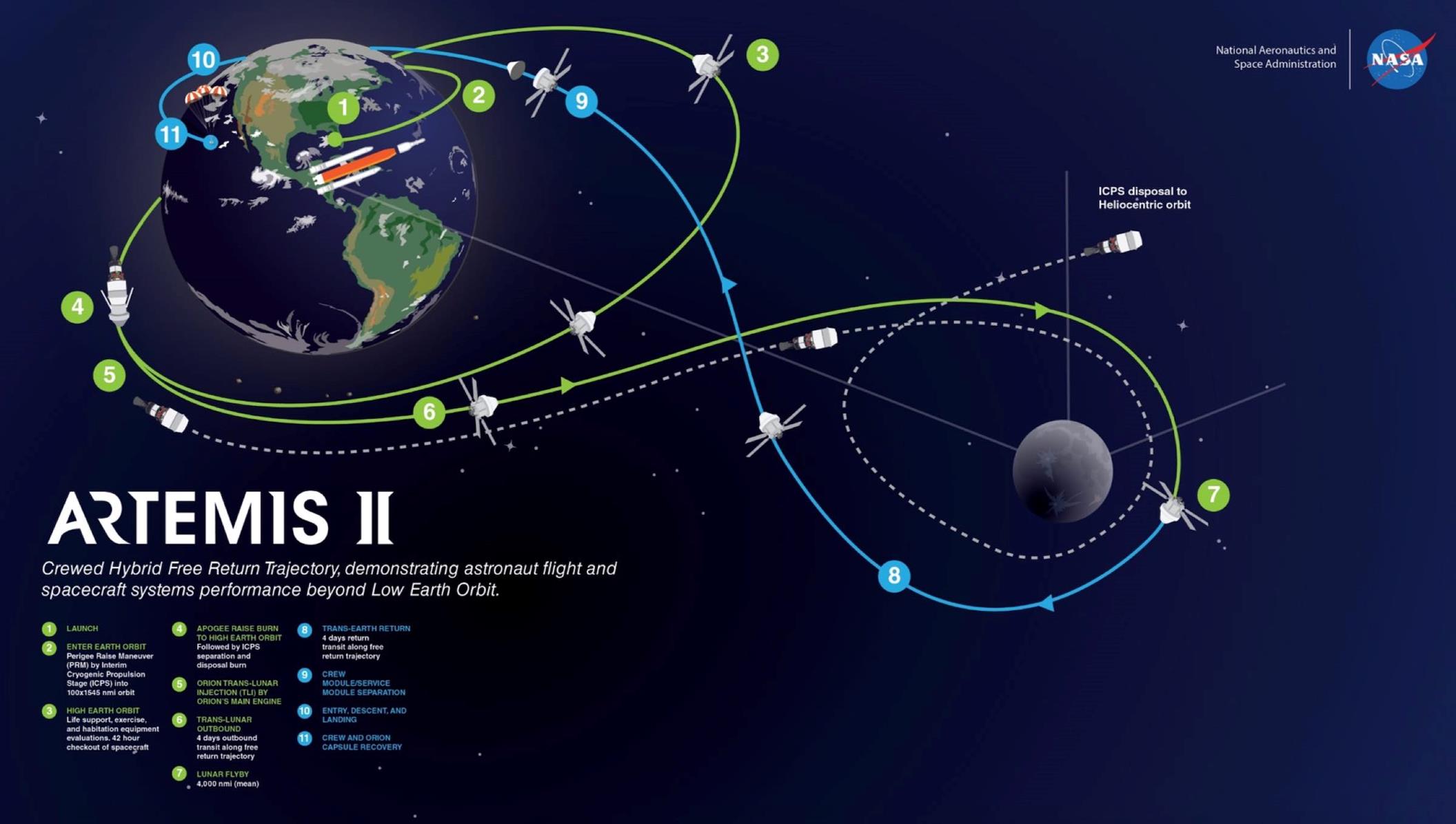
23 May 2020 Update-Addition
The above drawing is so badly distorted, it really is
deceptive. A better explanation
follows: The figure 8 free-return orbit
would look like this: The spacecraft
(and its mass to be exchanged with itself) is on the side of the Earth that is
opposite the moon (Hidden behind the Earth, below blue labels 10 and 11
below). To help boost it OUT of Earth
orbit and go moon-ward, following the green path labelled “6” below, while
hidden behind the Earth, it kicks out some mass slugs (or one big one maybe)
which will be given the exact same speed, but in the exact opposite
direction. In the direction of label 9
towards label 8, that is, on the blue path.
The large quantity of energy (length of acceleration track) to do this
thing (vessel kicking out mass slugs to go into the opposite-direction orbit)
would probably not be practical today, truth be told, but don’t forget, we’re
here to thwart patent trolls in the long-distant future!
The drawing below is stolen and re-purposed… Green path prograde stays pro-grade. Blue path (in our minds, for our purposes) is
changed to be a retrograde path.
The mass slug or slugs will now travel the BLUE path in
the drawing below, but in the exact opposite direction from the arrows shown
embedded into the blue path. At
green-label-spot “7”, the craft will meet up with its mass slug or slugs. The craft is far more massive than the slugs,
so the craft gets at least PART of the DECELLERATION that it needs, here on the
far side of the moon (opposite-away from the Earth), to insert itself into Moon
orbit.
The below drawing was lifted from https://spaceflightnow.com/2020/05/18/nasa-will-likely-add-a-rendezvous-test-to-the-first-piloted-orion-space-mission/ , which got the picture from NASA in turn.
Now the above figure-8-orbit scenario does deserve more
discussion. Suppose we wanted to save
the weight of so many tugs carrying so many large and heavy “space guns”
(accelerators and decelerators of whatever type). We COULD possibly put ONE LARGE such device
(guns pointing in both opposing directions, prograde and retrograde) in
permanent Earth orbit. This ONE LARGE
orbiting gun could be assembled in (fairly low) Earth orbit, and stay there,
for repeated re-use. It gathers energy
from solar collectors, and-or an onboard nuclear reactor, to power its
guns. Earth surface-launched rockets come
up to meet it in Earth orbit, of course.
It has a large-sized GENTLE (low-G-forces) pro-grade gun
to HELP launch large vessels, including passenger vessels, Moonwards. Additional propulsion power would have to be
added by more conventional means (rocket, ion, nuclear-thermal) for this to be
near-term practical. The other
(retrograde) gun nearly-precisely cancels the thrust imparted onto the guns
assembly, by the departure of the large, slow vessel. The retrograde gun shoots out, at high “G”
forces, mass slugs that are designed for delivery of high-G-forces-tolerant
cargo for the Moon. These “cargo slugs”
are given the orbital characteristics so as to NOT round the moon, but rather,
impact the surface. With the addition of
(for example) cold-gas thrusters, on these ME slugs AKA cargo impact vessels,
they could permit mid-course corrections, so as to hit a moon target
accurately. Alternately, both prograde
and retrograde guns could BOTH be assigned to shooting out only “cargo
slugs”. Delivery of high-G impacting
cargo onto the Moon’s surface is discussed thoroughly at http://www.rocketslinger.com/Hi_G_Cargo/ .
For
completeness, mentioned in passing, a permanently-moon-orbiting “antipode”
dual-gun station could also be used, for catching traffic from the Earth… Significantly (gently) slowing down a
passenger vessel here, by this means, sounds prohibitive to me (given today’s
“tech”). And yes, the slowing-down and
speeding-up functions (both ways) could be used on both the Moon end, and on
the Earth end. Just for completeness, it
has now been mentioned, and the patent trolls have hopefully been fended
off! But for the near-term practical
uses, the Earth-orbiting dual gun, prograde for slow vessels, retrograde for
cargo high-impact slugs, is what sounds to me, like it might actually be
practical.
The next scenario is even more speculative, and would
involve the expenditure of more reaction mass by the ME slugs. Suppose we have no conveniently located
two-body system to work with, like the Earth and the Moon, to perform the
“figure 8” maneuver with. An example of
this would be, we are approaching the Moon from an angle that is significantly
out of the “plane of the ecliptic”. The
tug could shoot some ME slugs towards the Moon at some semblance of a “free
return orbit” configuration, but the ME slugs will come back later to a spot
(perhaps) close to where the tug WAS, not where it is NOW, after time
delay. So that won’t quite work right,
without corrections (or another tug to interact with, to trade energies with, which
defeats our purpose of being independent).
Or think of a comet coming in at faster and faster
speeds, whipping around the sun, and coming back out. The comet is NOT going to cross paths between
its incoming path and its outgoing path.
(The comet here stands in for our ME slugs, and the Moon stands in for
the Sun, in this mental comparison). The
comet does NOT “round the sun” far enough to cross its former comet-path, that
is.
So, to make corrections for this, the ME slugs will have
to expend significant reaction mass in-flight.
Perhaps they can decelerate while incoming, to do a “partial orbital
insertion”, and then, time delay later, an acceleration to correct for it
(after having rounded the moon further than they otherwise would have, without
the “partial orbital insertion” burn).
Or, at Moon perigee, the ME slugs can perform outwards-directed burns,
so as to “prolong perigee”. Or, all of
these measures might be optimally combined.
Here’s a drawing (with small rockets to show the orientations of the
burns on the parts of the ME slugs) of what that might look like.
Figure
#7
Above and beyond spending reaction mass on the parts of
the ME slugs, the above scheme may have to make other compromises. The motion vectors of the tug v/s the
returning ME slugs may be fairly sub-optimal, depending on what all compromises
are made. The tug itself may have to burn
significant reaction mass to maneuver into an optimal position for reuptake of
the ME slugs. However, if we go lightly
on the re-acceleration burn, the ME slugs may be close to their apogee (and so
therefor at slower speed), meaning reuptake stresses on the tug will be
lessened. Would it all be worth it? I can’t say for sure! PS, the smaller the target body, the lower
its gravity, and the less stressful such an exchange would be, to the ME slugs
and to the tugs. This scheme, if not
suitable for the Moon, might be suitable for suitably moderate-sized asteroids.
“Mass
Exchange Dumps” Further in the Future
In the more-distant future, if space tugs using mass
exchange prove to be practical, and space travel is common, it may make sense
to put up artificial “mass dumps” as giant dampers, to simplify calculations
and traffic control for such space tugs.
That is, with huge masses, the mass dumps won’t move around so much,
when volleys of ME slugs are exchanged.
Space tugs can now exchange volleys of ME slugs with bidirectional mass
drivers located on these “mass dumps”.
Mass dumps could be made of de-tumbled asteroids and-or mining debris
(“slag”), or even other kinds of human or space-industry debris that isn’t
worth recycling. The mass dumps could be
maneuvered into position using mass drivers that are mounted onto asteroids,
flinging bits and pieces of the asteroid itself into space, as the propulsion
method (that idea has been kicked around for a while). If a mass dump is a “rubble pile”, it can be
wrapped in mesh (“chicken wire” if you will), and strategically reinforced by “mooncrete” (or the equivalent) at hardened spots. For a good read on Mooncrete,
see https://www.sciencedirect.com/science/article/abs/pii/S0950061811005903 .
Each mass dump should orbit the sun, or perhaps a major
planet in some cases (such as Earth especially). Mass dumps (sun-orbiting ones especially, and
especially in the inner solar system) should always face the sun, so that the
sunward side can efficiently use solar collectors.
Lagrange points will be the first and most obvious spots
at which to locate these mass dumps. See
https://www.thevintagenews.com/2018/11/20/hidden-moons/?utm_source=penultimate for an
introduction and a nice diagram. Starting
with L4 (leading the Earth’s orbit around the sun) and L5, then eventually L3
as well, place your “mass dumps” with Gauss gun emplacements added to the dumps. Note that L4 and L5 are most stable, and L3
isn’t quite so stable. As time goes by,
do the same to other planets’ orbits as well.
Now, whenever one needs a “boost” when going outwards in the solar
system, one is not limited to just using a “gravity assist” from only the planet
(Earth for example), but also, from 3 Lagrange points as well, and you can
boost your assistance-time-slots-count (L3, L4, and L5 mass dumps, via ME
slugs-exchange volleys, can multiply your one-and-only time slot for “gravity
assist” or virtual gravity assist via mass exchange) from 1 to 4. If we add (to each planet’s orbit) yet two
more pseudo-Lagrange-spot-located mass dumps halfway between L4 and L3, and then
again halfway between L3 and L5, we have now multiplied time slots from a mere
“1” to “6” instead of “4”. The
pseudo-Lagrange spots could easily be labelled “L6” (leading) and “L7”
(lagging), to stay consistent with the “real” Lagrange spots. L6 and L7 won’t be stable, but the needed
small corrective nudges (“station keeping”) won’t be all that prohibitively
large.
Figure
#8
In
the above drawing, if Earth is at 0 degrees out of 360 degrees, then “L4” is at
60 degrees, pseudo-L6 is at 120 degrees, L3 is at 180 degrees, pseudo-L7 is at
240 degrees, and L5 is at 300 degrees.
Earth then again is at 360 = zero
degrees, completing the circle.
So
gravity assists from the planet will remain as they are now. A gravity assist from a real planet can be an
outward boost (acceleration, travelling away from the sun) or an inward
sling-shot (deceleration, towards the sun).
Technically, due to the “no free lunches allowed” principle, every time
you get a boost from a planet (via gravity assist), you’re kicking the planet
backwards, closer to the sun. Every time
you “mooch off of the planet” to slow down instead, you’re speeding up the
planet’s orbit instead. No one cares,
though, because the planet’s mass compared to your spacecraft’s mass, makes
these effects vanishingly small, for the planet. The same will NOT be true of your “mass
dumps”, and the same “no free lunch” principles will apply! But here’s the good news: If the outward (spacecraft) traffic and the
inward traffic remain relatively balanced, they’ll largely cancel each other
out, and the per-mass-dump “station keeping” energies (and reaction mass) required
to compensate for this, will remain small, over time.
Once
again, ME slugs could be used to transfer cargo as well, so long as the cargo
being transferred isn’t too delicate, such that cargo would be damaged by the
high “G” forces involved. Our “mass
dumps” could easily become trading posts as well, then!
To
state what should be fairly obvious by now, when a space tug wants to get an
outward-travelling boost, it takes a route close to a mass dump, such that the
apogee of its orbit is close to the mass dump (with the apogee located just
barely outside of the orbit of the mass dump, with the tug being low in speed energy),
and the mass dump and the tug exchange volleys (of ME slugs) with the tug being
at the outer tip of what used to be its apogee.
They exchange volleys as the tug departs away from the mass dump, that
is, for tug acceleration.
Conversely,
invert everything… The tugs wants to
slow down for sunward (inward) travel.
It approaches the mass dump at the perigee of its orbit, with excess
speed. To kill its excess speed, the
mass dump and the tug exchange volleys as the tug approaches (not departs) the mass
dump.
The
same kinds of arrangements could be made with mass dumps located at Lagrange
spots at Earth’s moon as it orbits the Earth, or even at far lower Earth
orbits. At some point, socio-political,
safety issues will come into play…
Earthlings will worry about such mass dumps accidentally coming
careening into Earth! I leave the reader
to speculate for himself or herself, what would happen if NASA started
seriously working on an Earth-aerocapture maneuver
with an asteroid, to set up such a mass dump!
A casual “Google” search here told me nothing about such matters... I do recall people who worried about the
Obama-era scheme to capture an asteroid, and place it in a near-Moon orbit, for
these kinds of reasons!
Here’s
what will initially look like an unrelated topic diversion: See speculation about the use of
as-yet-impractical high-strength carbon-nanotube-based cables as a basis for
putting up a “space elevator”. See https://en.wikipedia.org/wiki/Space_elevator . I would speculate that such an engineering
effort is implausible for a long, LONG time to come, and that other, more
practical uses will be found for long, strong, lightweight cables far sooner
than this!
One
of these uses may likely be a more practical and affordable method of using
“mass dumps” for saving reaction mass, as we navigate the solar system. With this method, we need not carry heavy
“Gauss rifles” and “Gauss blunderbusses” to perform mass exchange with ME slugs. Instead, if one needs an outward boost, as
one approaches a mass dump, one shoots out a small rocket which spools out our
high-tech cable… Perhaps up to several
miles long. The mass dump does the same
thing to us. The two small rockets home
in on each other, and tie their cables together. Now, the mass dump will reel us in. If we do that at our apogee, we can now
travel outward from there, having saved reaction mass, at the expense of having
slowed the mass dump down.
Conversely,
inward-bound spacecraft can snare the mass dump via cables maneuvers… Note that the mutual snaring of cable-ends
will happen well away from both the tug and the mass dump, for safety… At spacecraft perigee, which will speed the
mass dump up. Advantages here are that
the travelling spacecraft can actually (inherently) fully dock at the mass
dump, and that forces can be gentle, if one or both parties continue to spool
out tether during a gentle slowing-down procedure (velocity-matching process). The spools and cables can probably be less
massive than “Gauss rifles” and “Gauss blunderbusses”, and certainly far less
awkward and gangly. If designed with a
reasonable amount of intelligence and foresight, the spools and cables can even
be carried on sleek, aerodynamic spacecraft capable of atmospheric re-entry,
which would be VERY difficult to do with the “space tugs” which have been
previously described (with the “Gauss guns”, etc.). The spools-and-tethers design is almost
definitely better (in some ways), actually, especially when given the existence
of the mass dumps.
Sad
to say, the spools-and-tethers method has a limitation: Due to the “can’t push on a rope” principle,
once the mass dump has snared an outward-travelling spacecraft, the spacecraft
is on its own for gaining yet more speed for yet further outward travels, and
the same or similar is true for deceleration, travelling further inwards (with
some additional convolutions, but enough of that for now). OK, so for that, we might be back to burning
reaction mass… Or perhaps giant,
compressed mechanical springs for ejecting the entire spacecraft back off of
the mass dump! Which does sound very
Rube-Goldberg-esque…
See https://en.wikipedia.org/wiki/Rube_Goldberg_machine . Or perhaps Wile E. Coyote-esque. https://en.wikipedia.org/wiki/Wile_E._Coyote_and_the_Road_Runner .
Unless
we swing the spacecraft round and round on the tether, faster and faster, then
let go, flinging it outwards (or inwards), SpinLaunch
style, and now we’d be imparting unwanted spin to the mass dump… More Rube Goldberg!
Speaking
of Rube Goldberg, there’s yet another problem that hasn’t been mentioned here
yet! We’ve spoken of the mass dumps
having to spend energy and reaction mass for orbital stability or “station
keeping”. However, they will ALSO have
to do the same with respect to spin stabilization! Even without using SpinLaunch-style
re-launching tricks! Whether we’re using
spools-and-tethers or ME slugs or both, in engineering terms, we’d have to keep
forces between spacecraft and the mass dumps in perfect balance with respect to
the centers of masses of the mass dumps. This will be impossible for practical
purposes, because the position-angles between mass dumps and spacecraft will be
in motion. Spin energy imparted to the
mass dump is the inevitable result. The
mass dump (unless impractically large) will thus have to correct for spin
stabilization… If not by shedding
reaction mass and energy, then by active spin stabilization using on-board
flywheels. More complexity, oh well… Maybe too complex? Well, the usual comment applies: At least we’re fending off the patent trolls,
in case these ideas ever become practical!
Keep
in mind that the most stable of the Lagrange points (L4 and L5) aren’t single,
fixed points, but rather, “clouds” around which “captured” items (human-made,
human-steered asteroids, or naturally captured asteroids) can orbit, in a
“cloud”. See Jupiter’s Trojan asteroid
clouds, for example, at https://www.nasa.gov/content/goddard/lucy-the-first-mission-to-jupiter-s-trojans … They move about 2 “clouds”; They’re not all
squished together into two single bodies.
It’s
likely that the most popular L4 and L5 Lagrange points (especially leading and
lagging the Earth) will eventually become major human habitats. Humans will not feel comfortably safe with ME
slugs and-or rocket-guided tethers flinging and zooming about nearby. So the “mass dumps” at such locations will
need to re-locate. The optimal orbits
for such mass dumps will likely be in small orbits circling the centers of the
Lagrange points, with the inclinations of these small orbits being at right
angles to the plane of the ecliptic.
That will maximize the desired safety here.
In the further-distant future, we might want to bring in,
closer to the sun, metal-rich asteroids, to be torn down and used for their
metals and precious metals. Metals will
be useful “out there” but most humans will want to stay closer to the sun… So that’s more-so, where we will want our
metals to be located. “Psyche” comes to
mind; see https://www.extremetech.com/extreme/289840-nasa-preps-mission-to-most-interesting-asteroid-in-our-solar-system . Psyche is too large… We’ll have to find a smaller metal-rich
asteroid, de-tumble it, and ideally, move it inwards in the solar system. After de-tumbling, we’d set up mass
launchers, take bits and pieces of the asteroid, and send the bits and pieces
careening clear out of our solar system, at the highest launch-speeds that we
can attain (presumably via mass drivers).
This will decelerate our chosen asteroid, of course, and bring it
inwards.
We
would also like to send robotic exploratory craft out to the stars… See https://en.wikipedia.org/wiki/Breakthrough_Starshot for example. In my humble opinion, this idea suffers from
too small of a payload… How will such a
small payload gather much information of significant value, AND broadcast it
back to Earth? A larger-sized craft
might serve us much better!
So
we have two needs: Decelerate a
moderate-sized metallic asteroid back inwards towards the solar system center,
and launch substantial-sized probes out of the solar system. We can kill 2 birds with one stone! (On a technical side, we’d ideally target
mostly other stars that are roughly on our plane of the ecliptic, but if we
deviate significantly from that, if we roughly balance our upwards shots and
our downwards shots, out of said plane of the ecliptic, the “push” inwards on
the asteroid will remain balanced). So then,
we manufacture “in situ”, as much as possible, interstellar probes, on our
metal asteroid, bringing in the most high-tech ingredients from the Earth and
the inner solar system. We launch the
probes from there, from mass drivers.
Many
variations are possible, but this is what such a scenario might optimally look
like: For simplicity, the asteroid is
equipped with outgoing mass drivers only, with respect to the interstellar
probes. There is NO two-way traffic (in
ME slugs) between the asteroid and the probes!
The mass drivers on the asteroid come in two flavors: One for the initial send-off of the probes,
and one for outbound speed augmentation of the probes in-flight. The mass driver for the probes themselves
might be rail guns instead of Gauss guns (or “other”, such as SpinLaunch style).
They’ll use relatively low “G” forces on sending out the probes
themselves. The probes need NOT be
designed for withstanding super-high “G” forces, which (low forces) increases
the usefulness of the probes. Relatively
delicate robotic data-acquisition gear MAY be enclosed in the probes, then!
The mass drivers (for speed augmentation) on
the asteroid accelerate SMALL-mass “ME slugs” at their maximum practical
speed… KE (Kinetic Energy) is treasured,
and momentum is relatively ignored! Now
in the EARLY phases of the probes’ flights, the ME slugs pass clear through the
centers of the “Gauss blunderbusses” on the probes… The probes “clutch at” the ferromagnetic-shelled
ME slugs as much as is possible, without endangering the probes, as the ME
slugs pass clear through the probes, slipping out the leading ends of the
probes’ Gauss guns, after imparting SOME of their speed-energy to the
probes. The probes do not “want to”
absorb too much speed-energy, as they might “regret” collateral damage of said
energies.
As the probes
travel further and further outwards, they pick up ever more speed, and the ME
slugs have a harder and harder time catching up with them. At some point, the probes are entirely able
to totally arrest ALL of the incoming ME speed-energy… And then the probes can reverse their “Gauss
guns”, and start throwing their captured ME slugs backwards, for additional
propulsion! (An on-board nuclear power
plant would be useful here, as well as for other purposes, such as sending data
back to Earth, after arrival at the target).
The probes may need to “wiggle” side-to-side a tiny bit, when casting captured
ME slugs backwards, so as to not bombard us left-behind humanoids in the solar
system, and (more practically) our mass drivers. Storing a “cache” of ME slugs on-board the
probe, before re-emitting them backwards, may stretch the postpartum blues
here, also, at the very end of ME slug reception. Don’t let go of those apron strings too soon!
Eventually the asteroid-emitted ME slugs won’t be able to
catch their targets any more, and then the launching process is done. Good luck and Godspeed, interstellar
probes! Call us when you get there! (Maybe we can get you to a substantial
fraction of the speeds of Buzz Lightyear before then)!
Well then, before I depart (for now) with you, dear
readers (in your millions and untold billions), I have just ONE more, final
associated futuristic prediction for you:
On board the afore-mentioned pseudo-Lagrange points at planetary “L7”
points, there will doubtlessly be our ever-faithful robotic emissaries,
always. There may also be
(rotation-styled periodically-rotated-but-perpetual, or camp-style
intermittent) human inhabitants. What,
you ask, will the anthem (theme song) of such human inhabitants be? I say, it will be “Wooly Bully”, by Sam
The Sham & The Pharaohs… Give https://www.youtube.com/watch?v=KZJiGu6Gz8E
a listen! For further clarification, see
the lyrics at https://www.google.com/search?q=%E2%80%9CWooly+Bully%E2%80%9D+lyrics&spell=1&sa=X&ved=0ahUKEwjA0YPXpojkAhVNmK0KHcbqD9QQBQguKAA&biw=1920&bih=888
. Don’t be an L7!
I have
no special expertise or any more plausible ideas concerning any associated
matters here, so I will sign off at this time.
This concludes my ideas as of this time.
Once again, comments or questions (or idea contributions) are welcomed
at RocketSlinger@SBCGlobal.net …
Stay
tuned… Talk to me! RocketSlinger@SBCGlobal.net
Back
to main site at www.rocketslinger.com