From RocketSlinger@SBCGlobal.net (please email me there; double-check the
link, it sometimes works poorly, it is supposed to be RocketSlinger
(spell it out) @ SBCGlobal.net).
Web site
last updated 20 July 2025
(In
decreasing order of potential interest to the readers, as judged by Yours
Truly)
Recently
hybridized with new release-dates actually
Link,
sub-page, Sociobiology Tribalism Etc: http://www.rocketslinger.com/SocioBio1/
Link,
sub-page, Testing Quantized Inertia: http://www.rocketslinger.com/Quant_Inert2/
Link,
Moon Impact Cargo and Artemis Accords: http://www.rocketslinger.com/RIFFLE/
Link,
sub-page, Quantized Inertia Drives: http://www.rocketslinger.com/Quant_Inert/
Link
to sub-page, LionGlass ArtGlass etc.: http://www.rocketslinger.com/LionGlass/
Link
to sub-page, Aerostats and Zombies: http://www.rocketslinger.com/Aerostats/
Link
to sub-page, COPVs Part 2: http://www.rocketslinger.com/COPVs_2nd/
Link
to sub-page, COPVs and the Aston Omega 1 Engine: http://www.rocketslinger.com/COPVs/
Link
to sub-page, Hi-“G”-Forces Impact Cargo Addendum: http://www.rocketslinger.com/Hi_G_Cargo_B/
Link
to sub-page, Shuttlecock Lift Body Re-Entry: www.rocketslinger.com/Lift_Body/
Link
to sub-page, Shuttlecock Re-Entry Power Management: www.rocketslinger.com/Bifrost/
Link
to sub-page, A Badminton-Shuttlecock-Style Re-Entry Method: www.rocketslinger.com/BadMinton/
Link
to sub-page, Hi-“G”-Forces Impact Cargo Methods: http://www.rocketslinger.com/Hi_G_Cargo/
Link to sub-page, Ping-Pong Mass-Exchange Spacecraft
Propulsion: www.rocketslinger.com/Ping_Pong_ME/
Link to sub-page, Remote (Moon, Mars, etc.)
Recycling of Rocket Exhausts: www.rocketslinger.com/Xaust_Recyclr/
Link
to sub-page, Passively, Thermally Gated Flow Switches:
www.rocketslinger.com/Psv_Tgt_Fsw/
Link
to sub-page, Variable Configuration Rocket Nozzle: http://rocketslinger.com/Var_Cfg_Rck_Nzl/
Link
to sub-page, Mountain Mounted Rocket-Launching Rail: www.rocketslinger.com/MntnMntdRcktRail/
Link
to fictional works by Yours Truly: www.rocketslinger.com/RocketManFiction/
Link
to sub-page, Turbine Spin Balancer: www.rocketslinger.com/turbine_spin_balancer/
Link
to sub-page for Icy-Words Lander, AKA Europa Lander: www.rocketslinger.com/Icy_Lander/
Link
to sub-page about a totally different field of endeavor: www.rocketslinger.com/SemiLamarckism/
Anti-Patent-Trolls
Magic Spell at www.rocketslinger.com/Near_Universal_Defensive_Publication/
Link
to Texas Art Concrete, AKA TexArtCrete, a Sole
Proprietor Art Business:
www.rocketslinger.com/TexArtCrete/ (Web
Page not very active, business is idled)
Hi, all of your rocketry and jet-engine fans! The below document was first “defensively
published” on 24 June 2012. The purpose
of this web site is to conduct “public domain rocket science”… I want to help develop new ideas in the
domains of rocket and jet propulsion.
AND I want to fend off the patent lawyers and patent trolls! Humans need to go out and start seriously
exploring the solar system, for starters.
Patent trolls are not going to help us…
So… Dear
Reader… Can you help develop these
ideas? Email me your ideas (including
critiques of the below), tell me if you want credit (or to remain anonymous),
and I will “defensively publish” your ideas also! If they are related to the primary targets of
this web site, GREAT! If you have
totally un-related ideas that you would like to defensively publish… Then I will be happy to post a link to your
web site. Or, if I find your ideas
fascinating (but un-related to jet and rocket propulsion), and you have no web
site, send me your ideas, and I can create sub-directories to this web site,
for you. We who oppose “patent trolls”
must all stick together! Email me!
Declaration of Legal Intent
I, Titus “Rocket Slinger” Stauffer, publish this with the
express intent of making all ideas contained here, that haven’t yet been
patented, available in the “public domain”, to prevent anyone else from
patenting them. The below is
“defensively published” in the name of the promoting the art and science of
rocketry and the engineering of rocketry systems, in a lower-cost manner. Excessive fighting over patents and patent
laws is not productive, and so here is my attempt to combat this waste of
effort. I have not stolen any secrets or
trade secrets from my employer (who is not at all in the rocketry business), or
from anyone else. I wish that no one
apply for patents on any new, unpublished, or unpatented ideas contained here.
Using Vertical-Rail-Mounted Jets for
Initial-Phase Launch Assistance for Rockets, and Using Outer-Wall-Mounted
Ceramic Turbine Blades
Titus “Rocket-Slinger” Stauffer, 24 June 2012
(Now being updated from time to time)
Abstract
Frankly, right up front, the author of this document
(first started in 2012) frankly admits that it is of low value. This is because the launch-augmentation
scheme is too complex, for too little gain (for the first 1,200 feet of ascent
only). Outer-wall-mounted ceramic turbine
blades would suffer from the following flaws:
This, sad to say, will
increase the spin inertia (angular momentum) of the engine pretty badly. One would ALSO face the problem of, WHAT kind
of material will we use to hold these blade-bases together, at the OD (Outer
Diameter)? Such “outer rim” materials
will be FORCED to resist very high tensile forces, at high heat! Centrifugal forces will concentrate hot,
compressed gasses there also. This whole
idea is therefore highly implausible.
This document is posted to ResearchGate, however, since the author wants
to briefly refer to it in a much newer paper.
This
is an only-moderately-formal document written by an electrical engineer who is
not formally schooled in rocket science.
Accordingly, the mathematics are kept to the
minimal essentials, and details are not provided in many categories. What is included here though, is a scheme of
several elements for assisting a rocket through the first approximately 1,200
feet of vertical launch. Four 1,200-foot
towers are arranged radially around the rocket and it’s
(conventional) gantry tower. On the face
of each tower (facing the rocket) is a large vertical rail. Inside the rail, there are solenoids that
open up, sequentially (vertically time staggered) opening up so as to release
pressurized JP4 (jet fuel), air, and water, in pulses that are received by an
ascending jet-propelled Jet / Elevator / Train (“JET” for short) assembly. The JETs climb the 4 faces of the 4 towers,
powered by 2 jet engines each. Since
they are fed JP4 during their brief upward journey, they need NOT carry all
their own fuel, and so they have a high thrust-to-weight ratio. From the JETs, downwards towards the rocket
(at a 45 degree angle or so), strong tow cables are attached. Attached to the cables, are also 2 hoses (or
sets of hoses), one carrying air and pressurized water, and one carrying
JP4. These hoses and cables meet a “cradle”
assembly that supports the entire rocket assembly (the rocket sits, cup in
saucer style, in the cradle, with minimal, if any, attachments between the
cradle and the rocket). The cables exert
upward force upon the cradle (and hence also to the rocket) during the first,
critical 1,200 feet of launch. For the
first 1,200 feet of launch, then, the cradle assembly will turn what is
normally the rocket’s nozzle, into a second combustion chamber. The rocket’s normal feed rate (rate of
injecting fuel and oxidant) can now be throttled down to a fairly small
percentage of what it would normally be, for the first 1,200 feet (saving fuel
or allowing for increased launch payload mass, of course). The first (primary) combustion chamber, for
the first 1,200 feet of ascent, needs only to burn enough fuel to heat the
secondary combustion chamber to the point where the air and JP4 will burn, and
these 2 sources of heat, together, will turn the water into steam, providing
additional expansive energy and propellant mass. The second combustion chamber receives “free”
JP4, compressed air, and water, that has been vertically pre-positioned in the
launch-assist towers (the rocket does not need to “burn the fuel to lift the
fuel” for this fraction of propellant mass).
The lift cables can provide some additional vertical thrust to the
rocket, yes. But their primary purpose
will be to constantly provide enough lift, so that the cradle assembly will be
kept mated to the rocket, without slowing the rocket down. At the end of the 1,200 feet, the cradle
slows down as the rocket’s feed rate goes normal (is “un-throttled” to maximum
or near-maximum thrust), and the rocket simply lifts up out of the cradle. Only the hoses at the injection points need
to be de-mated (in the same style, perhaps, as a gasoline hose de-couple when a
car driver drives away, forgetting the gas hose in the gas tank). And that added de-mating complexity is only
needed in one scenario.
Many drawings are provided here, to show how this could
work (along with variations of the scheme).
Calculations are reviewed that show that this scheme could reduce, by
about 4%, the weight of the rocket plus fuel, as it sits,
awaiting launch, assuming the scheme pulls 2 “Gees”. This does not include the mass of the cradle,
cables, and hoses, which, of course, stay behind. Also note, this 4% reduction mostly ignores
lift imparted to the rocket by the lifting cables. If the lifting cables carry a substantial
percentage of the mass of the rocket itself, the 4% reduction in rocket mass
(or payload mass increase) could be even greater.
At the end of this document there is also a discussion of
ceramic turbine blades and variable-geometry jet engines that convert over to
become rocket engines instead, through the use of turbine blades that partially
melt away (using “pyrometric ceramics” that have long been used in the
ceramics-firing industry).
Contents
A Brief Personal Note, and “Why”
Detailed
Discussions of Principles, Trade-Offs, and Alternatives
The “Lifting
Frame” Part of the “Cradle”, and Trade-Offs There
“Flying Off of
the Rails” is Indeed Hazardous!
More Details
About the JET Assemblies
More Details
About the Nozzle Extenders.
More
Alternatives for the Injectors and Injected Fluids
Trade-Offs
and Alternatives for the Over-All Scheme
A Short
Description of the Sequence of Preparing for Launch, and Launching
Solid-Fueled
Rockets and Aborted Launches
Ceramic
Turbine Blades for High-Speed Jet Engines, Mounted on the Outer Engine Wall
A Tour of More
Variations on This Scheme (to Include More-Fantastic, Science-Fiction-Like
Ideas)
Hybrid
Rocket / Jet Engines, or Variable-Geometry Jet Engines
Variable-Geometry
Jet/Rocket Engines, Further Notes, Updated 9-9-‘12
Variable-Geometry
Jet/Rocket Engines, Further Notes, Updated 11-10-‘12
A
Brief Personal Note, and “Why”
“Why” this document?
The intent is, first, to throw these ideas into the public domain (to
prevent anyone from patenting them). I
intend to “defensively publish” this document, that is. After that, the intent is for this document
to be posted to the web, to start a discussion about just exactly HOW these
ideas might most rapidly, economically, and safely be implemented (to hopefully
flesh out some more details, via “public domain rocket science”, if you
will). I, Titus “Rocket-Slinger”
Stauffer, simply want to see humans reach for the stars, ASAP! Why the “Rocket-Slinger” braggery? Well, simply, ‘1) it will serve as a handy
tag for a web site and an email address, and ‘2) it breaks up my name so that
web searches by my name will not easily tie me to the whole rocket-science
thing. I don’t want, in my personal and
professional life, to be (too easily or too endlessly) dragged into discussing
the whole rocket-science thing, or to be tagged as a whacko “rocket scientist
wannabe”, by people who lack serious interest in the topic. Serious discussions with fellow amateur and
professional rocket scientists and scientist wannabes, yes, that, I do
seek. Find me by topic on the internet,
not by my name, please!
Oh, yes, one last thing:
In seeking a compromise between personal braggery
and trying to stay to humble v/s bragging about my humility and actual quest
for privacy, trying to promote these ideas here v/s trying to tame the wild
speculative discussions and askance glances at the “space cadet rocket
scientist wannabe”, and so forth, I did want to mention that I’m a 1982
graduate of the USAF Academy. Former
cadet #826254, that’s me. ASAP, BMEWS,
AWACS, BOR, T-Shop, C-Store! My military
days are so far gone and removed from my current career that I suspect I can help
to gain just a tad of credibility by mentioning USAFA, and perhaps attract a
few web hits from fellow rocketry enthusiasts (maybe even experts) among the zoomies and ex-zoomies, while
also avoiding some negatives.
Introductory
Notes
What will follow is a description of a “primary path” for
this design, with little discussion of the exact details of the problems that
are being solved, or of trade-offs of costs v/s safety v/s efficiency v/s
environmental costs, etc. … Nor of problems being created by this design, and of how to
alleviate them. Discussion (in
this first, pared-down section) of alternatives and options will be kept to a
minimum. When, inevitably, minimal
discussion of alternatives and options creeps into this “primary path” design
description, these alternative ideas will be color-coded in BLUE so that the
reader may choose to easily skip over them.
Then following the “primary path” design description, there will
be a “detailed” section with discussions in greater detail, of alternative
implementations, and of design trade-offs.
Primary
Path Design
A bird’s-eye view of the launch facility would look like
the drawing below. The only thing
omitted (because it eats up a lot of space) is just a plain, empty field, in
which the 4 JETs (Jet-Elevator4-Train assemblies), with their trailing hoses,
cables, and launch cradle, can land, after flying off of the tops of the
launch-assist buildings. Alternative
scenarios would involve having the JETs brake to a stop at the tops of the
launch-assist buildings, and NOT fly off of the tops.
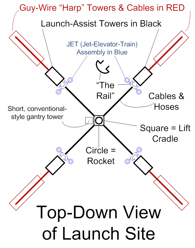
Figure 1 (above)
Working now from the outer periphery towards the middle,
essential elements will be described in more details, as needed. First, what are the “harp” towers? A side view of the launch towers and “harp”
towers may be warranted first. These
towers (for providing staying cables for counter-acting the lateral forces
exerted by the JET) are called “harp” towers because they look a bit like
harps, and the JET forces “pick one string at a time” as they travel up the
launch-assist towers. The launch towers
should be “smart buildings” with integrated strain gauges, and they should be
built to deliberately include a fair amount of flexibility. By allowing them to bend (flex), as the JET
travels upwards, the “harp” assembly provides countervailing force, primarily
focused a string (or a set of strings) at a time. Two drawings are provided below, one with the
system at rest, before launch, and one with the JET ascending the rail.
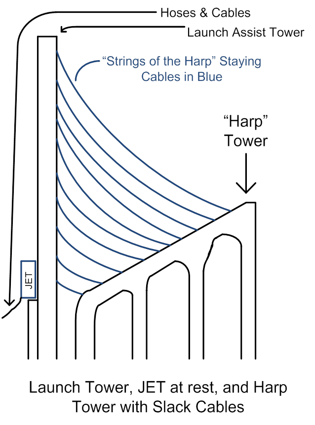 Figure 2 (above)
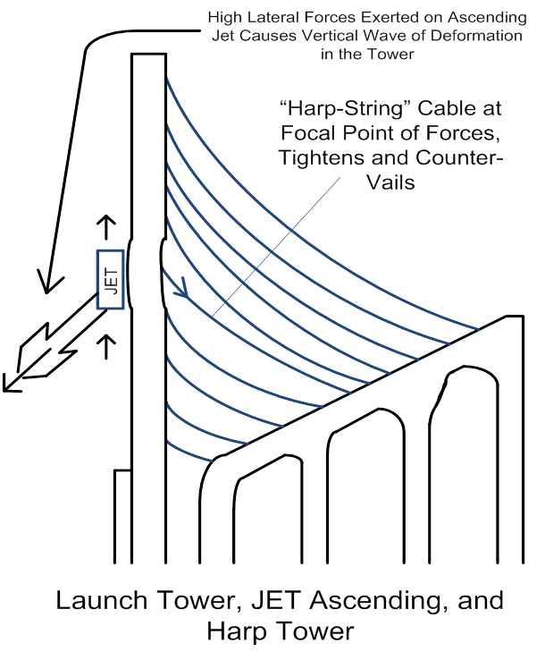 Figure 3 (above)
Continuing our journey inwards, covering the essential
elements, the launch tower and its vertical rail should be described next. It should be a “smart building” with strain
gauges on its main structural elements.
These strain gauges measure structural deformation (flexing, bending, twisting) caused by the JET and by wind-storms, earthquakes,
or other stresses. Thus, the building
can be cost-and-weight-reduced, if the “smart building” control system includes
being able to swivel the jet engines and to have the jets use vectored thrust,
to cancel any wild gyrations of stresses on the launch-assist tower. Optionally, in
wind-storms, the JET may be sent partways up the
tower (or even to the top of the building), to be started up, and to provide
countervailing forces against the wind.
Additionally, other smaller jets or propellers (JP4-powered,
electrically driven, or a mixture) could be installed at various heights and
angles, to be part of the “smart building” approach to survive windstorms,
while also reducing total structural costs.
Since the building almost definitely should be strain-gauge-equipped and
“smart”, for handling the stresses cause by the JET, then why not go all the
way (and cover environmental stresses as well)?
Obviously, a local energy source (for the jets and/or electric motors)
would need to be part of this scenario.
The vertical “rail” should be described next. A bigger-picture top-down view here,
necessary for making any sense of this, must also show a bit of detail about
the JET assemblies. For allowing the JET
assemblies to fly off of the tops of the launch-assist towers, and then to make
a controlled landing, the JETs may need some control surfaces. So the tower is shown to be narrow, so that
the JET airflow-control surfaces can overshoot the sides of the building. Note that the rail is hollow, accommodating
solenoids for injecting pressurized JP4, water, and air, into the ascending
JET. Also note that the JETs will be
equipped with automotive-style “brake linings” and the launch-assist towers
will be equipped with hydraulically activated “brake pads”. Why? For launch-forces control.
Throttling the thrust of the jet engines can be used as a part of the
control system for balancing the forces of the 4 launch-assist assemblies onto
the cradle and rocket (and ultimately for keeping the rocket itself balanced,
not toppling over), yes. However, jets
are slow to respond to their control forces (fuel and air input, etc.). Automotive-style hydraulically activated
simple friction brakes, on the other hand, have near-instantaneous
response. Thus, they need to be part of
the control system here.
Here is the top-down, rail-centered view of our “vertical
monorail”:
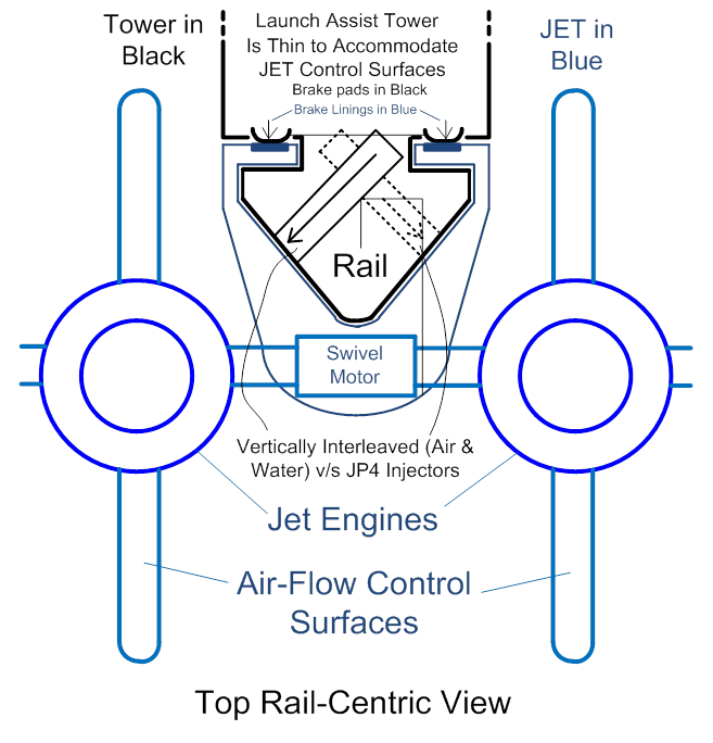 Figure 4 (above)
And then here is a further-away view just for more
clarification:
 Figure 5 (above)
One important detail has been omitted in the above rail-centric
drawings, and that is as follows: Since
the cables will exert high lateral forces on the “fuselage” of the JET, an
unacceptably high level of friction may occur between the rail’s lip and the
JET. The below drawing zeroes in on
where, exactly, rollers (long small-diameter wheels) should be place in the JET
assembly… Exactly opposite the brakes,
that is. Just like a car, we need both
wheels to eliminate un-desired friction, and controlled brakes to deliberately
add friction.
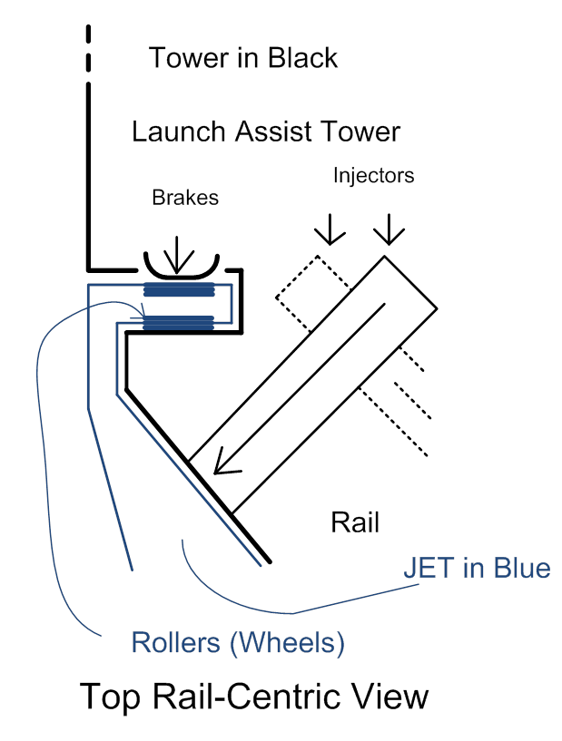 Figure 6 (above)
One
face of the vertical rail is dedicated to injecting a mix of pressurized air
and water into the JET assembly, and the other face is dedicated to injecting
pressurized JP4 (jet fuel). The
injectors are tilted to 45 degrees or so, so that upwards-squirting masses will
not unduly impede or burden the JET’s upward travel. If the masses were shot out in a purely
horizontal direction, then their zero vertical inertia would impede the JET,
especially as the JET travels rapidly at the very top of the tower. If the air, water, and JP4 is shot upwards at
sufficient pressures (and hence velocity), then (at least towards the bottom of
the launch assist tower, where JET velocity is still low) the squirted masses
may actually help propel the JET upwards.
Here is a side view along one of the faces of the
vertical rail. Arbitrarily, the JP4
injectors are shown, which are vertically interleaved with air & water
injectors. The water and air injectors,
then, are “squirting upwards into the face of the viewer” as shown here, and
their bodies are “dotted lines” when they go behind the JP4 injectors.
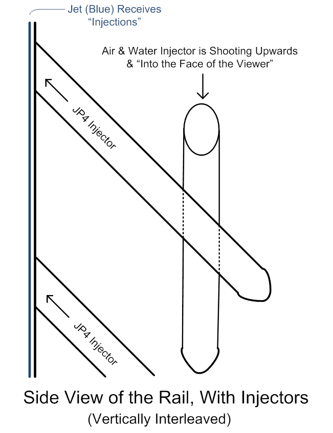
Figure 7 (above)
Details about the launch-assist tower are as
follows: Besides structural support of
the rail, the tower’s primary purposes are to pre-store air, water, and JP4 at
pre-positioned elevations. By storing
and pre-pressurizing this fuel and “reaction mass” ahead of time (by expending
electrical, chemical, and/or mechanical energy ahead of time, to pump up, or
pre-store, the energy of height or “potential energy” in the reaction masses),
the rocket is allowed to “cheat”, by using reaction mass that it does not have
to carry. The air-breathing jet engines
themselves, too, by their very air-breathing nature, briefly allow the rocket
to (indirectly) benefit from thrust derived by using oxygen and reaction mass
(air) for free, from the ambient atmosphere, which is not true of conventional
rockets. The launch assist tower also
supports the electronically controlled hydraulic brakes, which are needed by
the launch-control system.
No engineer worth his or her pay would consider
pre-positioning the water in one contiguous 1,200 foot water column,
because the water at the bottom would be horribly-highly pressurized (whose
handling would require excessively high-cost, high-strength, and heavy tanks
and/or hoses). The same is true of the
brake fluids for the hydraulic brakes, and for the JP4 (and to a lesser extent,
even to pressurized air). Also, as the
JET travels faster and faster, towards the top of the rail and tower, it would
be good for the pressurized masses to be injected at higher and higher speeds
(backed up by higher and higher pressures, which is the exact opposite of what
one gets with a tall column of fluid in a gravity field). So for these reasons, all of the pressurized
fluids (or incompressible fluids backed up by pressure-providing gasses or
pistons) need to be vertically segmented (in, say, 50-foot increments).
Immediately preceding launch, the jet engines should
already be revved up. They can already
be straining their lift cables, “chomping at the bit”, with each
assist-tower-assembly providing, say, 10% of the lift needed to hoist the
entire rocket (total 40% for the 4 towers, adds up quickly!). They (jet engines) obviously can benefit from
some fraction of the pre-stored JP4 available to them, through the injectors
embedded in the rails, while some other fraction of this JP4 is dedicated to
feeding the rocket itself (via the hoses suspended by the lifting cables). What is less obvious is that even the jet
engines themselves could sip a bit at the vertically pre-stored water
supplies. Throwing water into a jet
engine is a lesser-known but very effective technique for gaining additional
thrust.
In any case, the already-straining, preparing-for-launch,
but still-stationary jet engines can be supplied with fluids/fuel/supplemental
reaction mass, via slow-reacting, relatively inexpensive solenoids. Solenoids open up to permit the flow of
fluids to the JET, and as soon as the JET moves up out of its initial position,
the solenoids (and fluids) shut down.
For the first few feet of ascent, the reaction speeds of slow, cheap,
conventional (electrically or otherwise activated) solenoids will be fast
enough to match the slow ascent rate of the rocket. That is, solenoids open up as the JET slides
upwards to receive what the tower and its rail “inject” into it, and shut down
afterwards, fast enough to be efficient (and not spill any significant amounts
of the fluids).
Very rapidly, though, the rocket’s ascent rate increases,
and the conventional, slow-reacting solenoids will not be able to keep up (the
solenoids open up too slowly, and shut down too slowly, to match the ascension
rate of the JET). Fuel or reaction mass
is spilled. For pressurized air and
water, at middle elevations of the tower, this is (perhaps) fairly tolerable. Note that one face of the rail is dedicated
to injecting JP4 to the JET, and another is dedicated to injecting a mix of
pressurized air and water. Air and water
are cheap… And they shoot out at an
angle that is NOT directed straight at the rocket (downwards-draining water
spray hitting the rocket will not “parasitize” the ascension of the rocket,
since the injection angle mismatches the direction to the inadvertent “target”;
“target” being the rocket). So,
slow-reacting, cheap solenoids may be tolerable for spilling a bit of
pressurized air and water, at least at middle elevations. On the other hand, suspending the weight of
pressurized air (and then far more so, water, which is much heavier) just to be
wasted, at the upper reaches of the tower, may rapidly become cost-prohibitive
(in terms of extra strength and mass, and of course costs, of the tower). So even though SOME spillage of pressurized
air and water may be tolerable at middle elevations, it may be necessary to go
to more high-cost (and quicker-reacting) solenoids at the highest elevations,
even for (harmless, inflammable, non-explosive) air and water. JP4, on the other hand, DOES provide some
hazards in terms of flammability, and even in terms of explosions. So, just about ZERO leakage is tolerable
there, and slow-reacting, cheap solenoids will VERY rapidly need to migrate
over to faster-reacting, more-expensive solenoids, on the upwards journey.
Let’s cover the case of the pressurized air and water,
first. The case of the jet engines
straining but still at rest, and of slow solenoids opening and closing as the
JET ascends slowly, at first, hardly needs to be diagrammed at all. Which leads then to the middle elevations,
where (depending on economic analysis of the costs of a stronger building to
hold more mass of water, some of which will be wasted, v/s the costs of
faster-reacting solenoids) it may make sense to build a scheme under which
pressurized air and water is released as diagrammed below. In vertical segments (each, say, 50 feet
tall), a water-fall column is fed by spray nozzles, with some water collected
at the bottom of the waterfall, and pumped back up to the top of the tank. The entire assembly (tank and waterfall) is
highly pressurized. As the JET ascends,
solenoids in the rail open up, allowing a mix of pressurized air and water to
flow into the JET.
The below drawing shows heavier blue line widths in the
arrows in the middle of the JET assembly, for pressurized air and water
injections, which is meant to show that this matches the maximum opening of the
solenoids (max flow rate to coincide with JET position). Cheaper, slower-reacting solenoids being used
here, though, may mean that there will be some spillage before and after the
JET is in proper position. Air and water
are cheap, though, so some spillage should be acceptable.
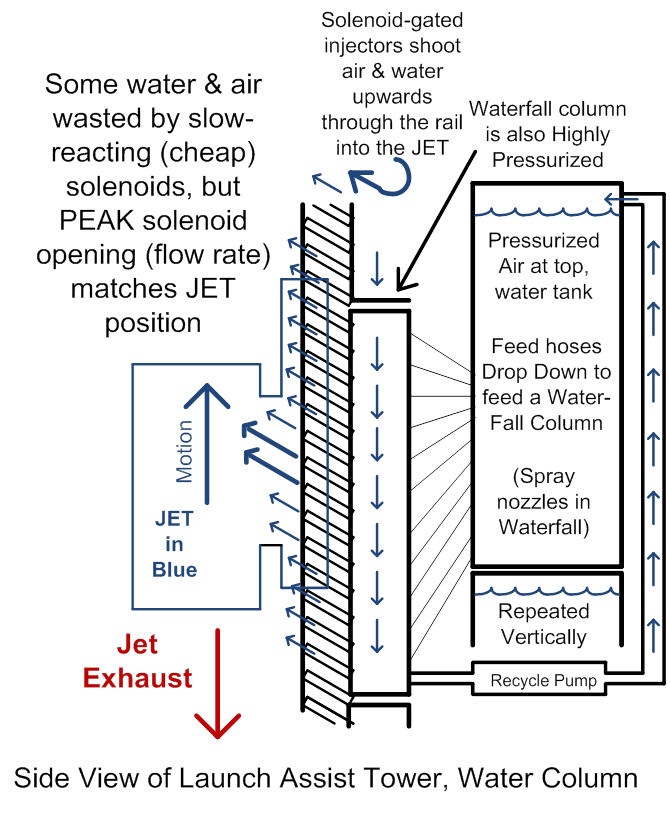
Figure 8 (above)
At higher and higher elevations, though, the JET will be
travelling ever faster, spillage rates (assuming slow, cheap solenoids) will
increase, and spillage costs will increase, since it is costly to build a tower
to suspend, at high elevations, the mass of large amounts of water (especially
just to be wasted). So the costs and
engineering trade-offs will start to dictate that more expensive, but
quicker-reacting, and less wasteful, solenoids should be used for the
water. Water injectors could be vertically
interleaved with air injectors that are injecting purely nothing but compressed
air (which is not as dense and therefor expensive to house in the tower; we can
afford to waste pressurized air, even at high elevations). For the high-elevation water injectors, the
best choice might be to borrow from the automotive industry. A mixture of air and gasoline is injected
into a combustion chamber well ahead of time, and a spark plug ignites it at
the precisely correct time to power a piston, shooting the water up into the
JET. Just like a car engine, this
require precisely machined good-quality tool steel, but the costs may be
justified at the higher elevations.
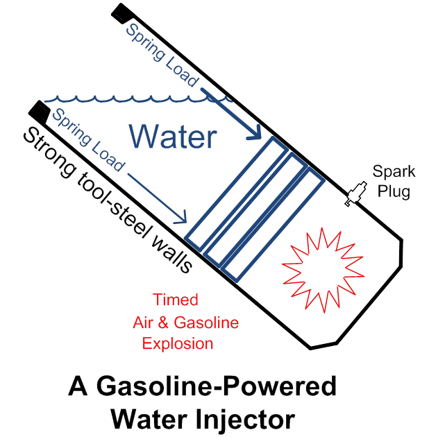
Figure 9 (above)
Note that in addition to being more expensive, per
injector, this scheme also requires more preparation work… Every injector has to be loaded with water
before each launch. Also note that it
would probably be a good idea to spring-load the chamber, so that the plunger
will return to the “down” position after the injection shot, to prepare it for
re-loading. An
alternative to gasoline explosions might be gunpowder or other explosives, but this
is probably not a good idea, for many reasons; costs, environmental, &
safety.
For the JP4 (jet fuel) side of the rail, spillage of JP4
will not be at all tolerable. Spilled
JP4 is expensive, dangerous, and an environmental hazard. Accordingly, for all but the very lowest
elevations, cheap, slow-reacting solenoids will not do. The gasoline-powered injector should be used,
with a few changes: JP4, unlike water,
is expensive, and vaporization (out-gassing) is hazardous. So the opening of the JP4 injector (the
“muzzle” of the “JP4 cannon”) should be gated by a cheap solenoid… Slow-reacting is fine. It would be opened, say, several seconds
before the gasoline detonation (a few seconds of out-gassing of the volatile
compounds in JP4 should be tolerable).
Otherwise, it would be highly similar to the “water cannon” shown
above. Also, during the filling
operation way before launch, a nitrogen-gas feed line should fill the air gap
(for fire suppression). Then between the
time that the slow-reacting “muzzle solenoid” opens, and the gasoline explodes,
nitrogen should again be fed to the air gap, for keeping ambient-air oxygen
away from the JP4 as much as possible.
All injectors should be as precisely timed as is
reasonably possible. This timing is
hardly a major challenge to modern electronics…
Precise positioning could be determined by Hall effect
sensors, laser interferometry, LEDs and photo sensors, or any other kind of
proximity detection apparatus distributed in the rail and in the JET assembly.
Alternative variations to the scheme discussed
here, would be to “spike” the water with oxidizers and oxidants. On 2 out of the 4 launch-assist towers,
oxidizer could be added to the water…
Hydrogen peroxide would be a very good choice, or perhaps ammonium nitrate. On the other 2 towers, ethanol, methanol, or
emulsified petroleum products (oxidants) could be added. More exotically, even methane clathrates
could be added to chilled water, although that’s very likely to be
impractical. The two “flavors of water”
finally meet each other and react, only in the rocket engine, so the extra
safety hazards (especially if concentrations are kept low) might be tolerable. Costs and environmental hazards would tend to
prohibit the idea of tolerating spillage (with cheaper solenoids), though.
This leads us, next, to the JET (Jet-Elevator-Train)
assembly. It would (on each side of the
rail, one face of the rail for pressurized air & water, one for JP4) need
to have a funnel to receive the highly pressurized (high velocity) fluids. At the top of the funnel would be an assembly
familiar to many farm boys… A strong,
rigid “goose neck” designed, much like the assembly on top of a silo-feeding
metal silage chute, to re-direct high-velocity silage down into a silo. Except the goose-necks here are re-directing
JP4 in one case, and high-velocity aid-water mix in
the other, to flow down into the hoses.
The paths to the funnels would be un-obstructed with respect to the
timed injections from the rail. Above
and below the funnels, however, deflection louvers would be tilted to receive
the forces of any spillage (leading and lagging the fairly but not perfectly
timed injections) of injected fluids, which then drip down to be blown up the
funnel, or collected at the bottom of the fluid-receiving dual funnel
apparatuses in the JET. The spillage
collected at the bottom of the JET is pumped into the hoses leading slant-wise
down to the rocket. These 2 pressurized
funnel apparatuses are sealed away from each other, so that the oxidizer (air
on one side) does not meet the fuel (JP4 on the other side). The funnel apparatuses (just like the hoses)
are pressurized with respect to the outside world, to hasten the journey of the
fluids down to the rocket. They are not,
however, as highly pressurized as the being-injected fluids, so that all fluids
are sped, at high speeds, through all legs of their journey.
Figure 11 (above)
The body of the JET will need to be strong and highly
resistant to bending (probably tool steel in major structural elements), so that it can meet the rail with minimal tolerances
(mechanical mis-matches). If tolerances are too tight, friction
(resistance to motion of the JET along the rail) builds up. If tolerances are too loose, leakage of
pressurized fluids will go out of control.
1/8th or 1/10th of an inch or so (gap between rail
& JET) might be the right target.
The rail surface will need to be greased, pre-launch. Some leakage of pressurized water and air
should be quite tolerable. Leakage of
JP4 to the outside world, in small amounts, can be tolerated also. A fire-suppression system along the rail can
be implemented, and spillage of JP4 (that amount that does not vaporize, at
least) can be collected at the bottom of the tower. However, accidental leakage of outside air,
into the body of the JET, especially into the interior of the JP4-receiving
funnel and louvers apparatus, would be an un-acceptable fire or explosion
hazard. Accordingly, the JP4 funnel /
louvers area should, during its ascent, be pressurized
by the timed release of a liquefied, super-chilled inert gas. Liquid helium would serve as a VERY inert
gas, but liquid nitrogen would do the job almost as well, more affordably. The inert liquid nitrogen would be dispensed
to both suppress heat, and to highly positively pressurize the funnel chamber
on the JP4 side, to resist invasion by external, ambient air. Liquid nitrogen, of course, will expand into
a gas as it heats up. Both effects would
suppress the likelihood of accidental fire.
The liquid nitrogen would be carried all the way through the ascent of
the JET, inside the JET, providing minimal burden to its thrust-to-weight
ratio. Alternately, JP4 could be
injected intermixed with large amounts of pressurized nitrogen, through the
rail, or JP4 injectors could be vertically interleaved with a few nitrogen
injectors, but the extra expense and complexity is probably not worth it.
The JET, as previously mentioned, would have a swivel
motor (air pressure powered from the jet’s compressors, or electrical powered)
embedded in it, to allow the two jet engines to swivel their thrust alignment
to be more vertical or less vertical, as is needed. Here are a few more drawings to clarify what
the over-all JET assembly might look like.
Note that in the prime scenario described here, the
whole assembly of JETs, hoses, cables, and rocket-assist cradle would fly clear
off of the tops of the towers, and need to make a controlled vertical landing
afterwards. So, the JETs need a
reserve tank of JP4, as well as telescoping (perhaps air-pressurized) landing
legs. Alternately, the brakes
would be used to slow down the JETs as they approach the tops of the towers, so
that the JETs do NOT fly off the tops of the towers, but that means their
ability to assist the rocket is truncated towards the end of their ascent, and
leads to other problems as well. Note that the jet engines in the pair, on one
JET assembly, need to counter-rotate with respect to each other, so as to
cancel out torsion, or twisting effects onto the JET body, as the engines rev
up and down.
The JET assembly drawing above shows the funnels further
up and the swiveling jet engines further below, in other words. The above drawings have so far implied that
the funnels might impede air-flow to the engines, though. All of these drawings are purely
conceptual. In reality, the engines
should be further separated, to allow them un-obstructed air-flow, and to more
widely space their air-flow control surfaces…
Also allowing the launch-assist towers to NOT be
forced to be very skinny. Note
that the tow cables should also be attached to the part of the JET body that
has to be heavily-enough built to support all the thrust of the engines. Here is a further-away top view to clarify
these items:
Figure 13 (above)
Not to belabor the things that should be obvious, but the
rotating true axle should be encased with a non-rotating sheath, which should
also have some reinforcing truss-work back to the JET “fuselage” for extra
strength. The sheaths should only stop
when it almost touches the jet-engine assemblies, to allow the engines to
swivel, and the sheaths should also carry JP4 fuel lines, controlling
electronic wires, and electrical power (generated by the jet engines) for use
in the “fuselage”. The sheaths also
support the tow cables; they are clearly the focal points for major forces and
stresses, from the tow cables and the jet engines, and so they will need to be
heavily built. Here are side drawings of
the JET assembly, minus the air-flow controlling fins, for clarity. Complexities like side hoses for feeding JP4
to the engines are omitted. Note the
presence of extensible legs for vertical landing.
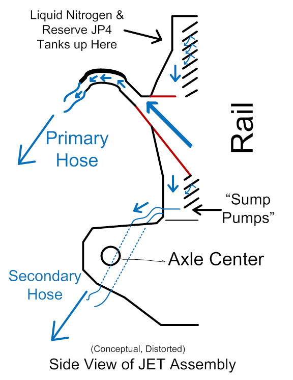
Figure 14 (above)
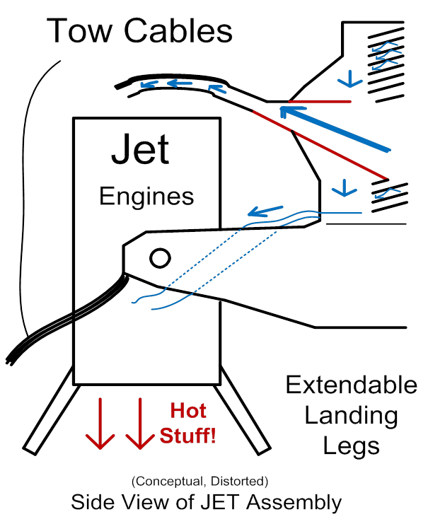
Figure 15 (above)
That now covers the essential elements of the JET
assemblies. Next come
the cables and hoses (as we continue our journey from the outermost elements
towards the innermost). Very few
diagrams are needed here. The cables should be derated
to cover several times more than their expected loads. If, for instance, each launch-assist tower
plus JET assembly exerts 10% to 15% of the weight of the rocket (to keep the
cradle forcibly mated to the rocket) of upwards lifting force on the rocket,
then the cables, per tower, should be able to lift or suspend 50% or more of
the rocket’s weight. Cables should be
periodically inspected for degradation, obviously, and there’s not much more to
be said there.
Hoses will be attached to the tow cables for mechanical
support. Hoses should be derated for pressures to be handled, “TBD” (To Be Determined;
this author is not smart enough to tell the reader what PSIs, Pounds per Square
Inch, of pressures should exist at various stages of the fluids’ journeys), and
periodically be inspected and tested as well, just like the cables. Here, there is a less-obvious factor to be
considered, for the hoses, though. That
is, when gasses and liquids are intermingled, as air and water will be, in one
hose or set of hoses, and JP4 and nitrogen or helium in the other hose or
hoses… Please recall the afore-mentioned
safety measures… Then gasses v/s liquids
tend (via surface tension effects if nothing else) to “clump”, or
segregate. This will not be good for the
rocket engines that are ultimately being fed.
So, for lack of anything else, better, to call them, periodically,
throughout the lengths of the hoses, “apple corers” or gas / liquid re-mixers
will be periodically be embedded inside the hoses. Think of a razor-edge “apple coring” device
that you might keep in your kitchen.
These will periodically, during the travels of the liquids and gasses,
in their journeys down the hoses, be embedded inside the hoses, to prevent
“clumping”. A single drawing should
suffice:
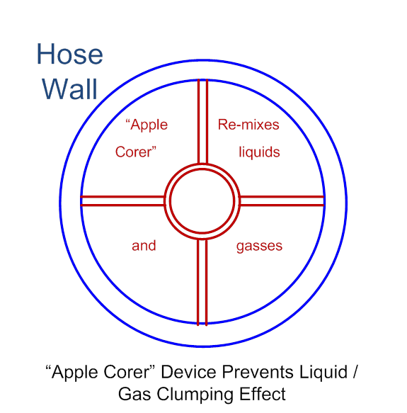
Figure 16 (above)
2 March 2013 update:
Hi all of you rocketry and jet propulsion fans, I have finally received
an un-solicited email relating to the business (topics) of this web site! A manufacturer of hoses (suitable for uses as
here described) emailed me. So I hereby
grant them some free advertising, here is their contact information. Following that, is my email response to them,
asking about the proposed device shown above in figure 16. I don’t have a budget to develop the ideas I
show here; Bill Gates has NOT yet offered to fund my ideas! But discussions about the
ideas here, and where to buy suitable parts or materials? Yes, absolutely, let’s get those
conversations going!!!
CHINA ATAMAN IND. LTD.
WWW.HOSEOK.NET ATAMANHK@GMAIL.COM
Hi Mr. Tung,
I got your email a while
back and am now finally responding.
Apparently you have actually glanced at my web site at www.rocketslinger.com and have
noticed that I mention uses for fire-resistant industrial-grade hoses. I have added your contact information to my
web site, as the least I can do for you.
Sad to say, I have no budget to actually spend on high-pressure hoses,
or anything else I describe in my web site, I am just an amateur fan of
rocketry and jet engines… And I also
want to help fend off “patent trolls” in this particular type of
technology! … So anyway, no, sorry, I have no money to
spend buying your hoses. If you do have
spare time to look some more at my web site, please look at “Figure 16” (use
that as a search string). You see that I
have proposed a method of periodically mounting an “apple corer” style liquids
and gasses re-mixer, inside the hose, so that liquids
v/s gasses “clumping” would be prevented (globs of liquids would be
periodically re-mixed with the gasses, if the mix is flowing at high
speeds). Perhaps some would call this a
“homogenizer”… Is this something that is
done in the hoses industry? Is there a
better way to do this? Is there a
special term for such things? I can’t
buy from you, sorry… But I am interested
in the industry. If you care to respond
to this, I will be surer to post your response on my web site.
Thanks! -Titus, AKA RocketSlinger@SBCGlobal.net
… Back to original web site
materials now…
Air
intermixed with water is not a problem, it will help
to oxidize the JP4 as the fluid masses are injected into the rocket
engine. Nitrogen gas intermixed
with the JP4 contributes nothing other than inert reaction mass, and so, if
desired, should be separated out from the JP4, at least partially. Part-ways down the down-sloping tow cables…
Or down at the cradle area or mounted on the nozzle extender walls… With NO
anti-clumping “apple corer devices” between the JET and this “separator tank”,
on the JP4 fuel line… A tank would allow gravity/acceleration and spin
separation between the JP4 and nitrogen gas, with the gas being bled (most of
it at least) off of the top of the tank.
This tank should ideally be funnel-shaped, with the fast-flowing JP4
directed downwards in a spiraling motion along the sides of the funnel; small
funnel end down, large funnel end up, gas-bleed valve to the top middle of the
funnel. Then the anti-clumping devices
can be inserted further down the JP4 line, to keep the JP4 intermingled with
whatever remaining nitrogen gas that makes it through the separation tank.
Hoses
and cables are now at least summarily covered.
Next comes the rocket’s “cradle”, which
encircles the base of the rocket, and supports extensions to the rocket
nozzles. The nozzle extensions will be
covered first. For the sake of simplicity,
only one rocket engine will be shown at first, but the whole scheme here could
apply to a multi-engine rocket as well.
Admittedly, when the number of rocket engines gets up past 4 or 5, the
plumbing would get difficult, in order to add extra reaction mass to engines
that are in the middle of other rocket engines.
Here is a side view of a single-engine assist scheme:
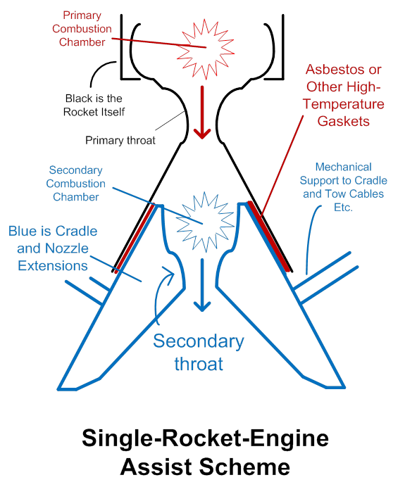
Figure 17 (above)
The above drawing shows (in heavy blue lines towards the
bottom) hollow shapes for the nozzle extensions. These should actually be three-dimensionally
honey-combed structures for compromising between weight and strength. Note the presence of gaskets between the
walls of the nozzle extensions (which of course stay behind on Terra Firma
after the brief ride up as assisted by the rocket-assist towers etc.) and the
walls of the rocket’s original nozzles.
The gasket falls away when the nozzle and the nozzle extensions part
ways. The gasket is needed for
preventing the escape of hot gasses due to mechanical mis-matches,
and for protecting both the true nozzle walls, and the nozzle extension walls,
from abrasion due to mechanical shock and vibrations. Asbestos can be used if no other suitable
materials can be found, but only if permission from the health and safety NAZIs
can be obtained, or if the rockets are built in a nation with more appreciation
for common-sense compromises between engineering effectiveness, and
environmental regulations, than is available in the USA today.
Note that some rockets (such as liquid-oxygen and
liquid-hydrogen fueled NASA rockets) do not have a “throat” or a combustion
chamber that is different from the nozzle or expansion area; for these rocket
engines, the nozzle (expansion area) is the one and the same as the combustion
chamber. There, liquid fuel feed lines
are embedded into the nozzle walls, to simultaneously cool down the nozzle
walls, and to pre-gassify (pre-heat) what was
frigidly cold liquid, to become flammable gasses. In this scheme, the high-temperature gasket
would prevent the bottom-most fuel-feed lines from feeding the fires, during
the assistance-launch phase. This is a
good thing, since (during the assisted-launch phase) we want to save (be
miserly with) the primary rocket’s fuel, anyway. There would be only one combustion chamber,
not two. After the nozzle extensions and
the gasket falls away, the bottom-most fuel-feed lines would then be available
for powering the rest of the rocket’s ascent.
That scheme is not much different than the first, but here below is a
drawing. Also note that since this
drawing is simpler than is the case with the two combustion chambers and the
two constriction throats, it (the simpler case) will be used in subsequent
drawings.
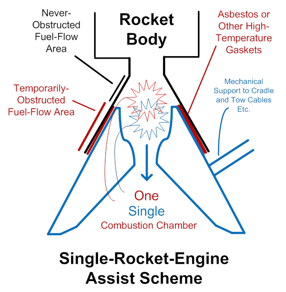
Figure 18 (above)
As far as handling a multiple of rocket engines goes, if
the number of engines is small, separate nozzle extensions can be used (some of
them may be a bit misshapen at the bottom, or
truncated in their innermost walls, at the bottom). In other words, only at the outermost walls
of the clumped-together nozzles extensions or unified nozzle extension, only
there, would the nozzle extension wall need to reach the ground, pre-launch, for
weight-bearing purposes. The inner dividing
walls can be truncated, and the unified expansion area is still highly
pressurized by escaping super-hot gasses, propelling the rocket (plus assist
cradle and nozzle extensions) upward.
Note that in the below drawing, a constriction “throat” is still added
to both engines, during the assisted ascent phase, so as to maintain high
enough pressures and temperatures to burn up the added, injected JP4 and
pressurized air (and to vaporize the injected water as well). Without the constriction throat, temperatures
and pressures in the combustion chamber are too low.
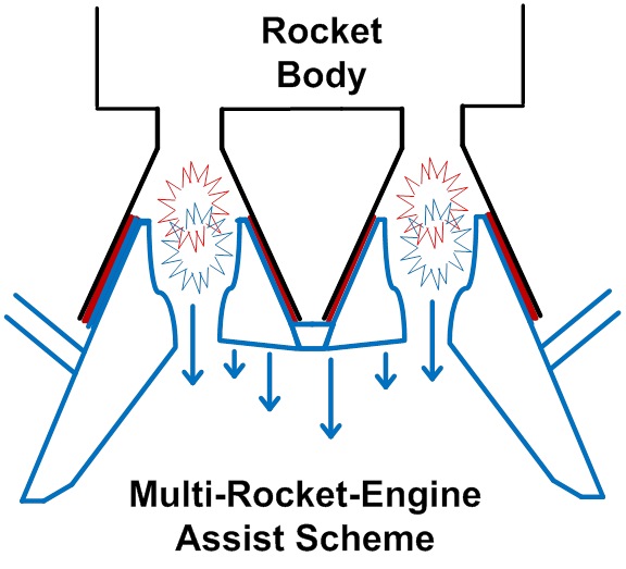
Figure 19 (above)
If we go yet higher in numbers of rocket engines, then
only the engines on the outermost edges of the clump of engines,
can easily be “plumbed” to bring them additional reaction mass. Accordingly, only the outermost ones will
have “plumbing”, and only the outermost ones will have “constriction throats”. As shown below… Red explosion-signs mean powered by rocket
fuel carried by the rocket itself, and blue means using “imported” reaction
mass from the assist scheme, please recall…
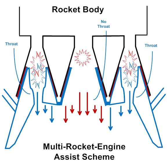
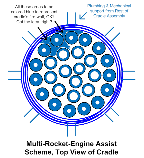
Figure 20 (above)
A top view of the cradle and nozzle extensions is hardly needed for the single-engine scheme. However, with a high number of rocket engines being supported, the design can get confusing. So here is a top-down drawing of this. The outermost, very heavy blue lined circle represents the outermost walls, that touch the ground for weight-bearing purposes, and encompass the entire hot-gasses expansion area, for lift. The black circles represent where the rocket nozzles touch the cradle / nozzle extender. The outermost rocket engines can easily be fed extra reaction mass, and so they show constricted throats (blue, smaller circles inside them; open white holes being the insides of the “throats”). Innermost engines do not (they show only minimal blue inside the black circles, where blue walls meet black walls, vertically, where cradle / nozzle extender meets rocket nozzle walls). Innermost circles show wider white holes, meaning no throat constrictions, that is. Filled-in blue areas (not all filled in, this author is too lazy!) represent the structure of the top of the cradle, where the cradle / nozzle extender assembly top, creates a fire-wall between the unified expansion area, and the rocket. A ridiculously high number of rocket engines is shown to demonstrate the general principles.
One single top view of the bigger picture, for the entire
cradle assembly, should suffice. The
number of launch-assist towers could be other than 4, but 4 is assumed in this
primary design description, so 4 is shown. The cables-attached structural element could
be called the “lifting frame” and should be square for 4 launch towers, 5-sided
for 5 towers, and so on. The “lifting
frame” could be hollow for re-distributing reaction-mass fluids, but doing so
means re-directing the fluid-flow motions (impeding flow). The number of “struts”, then, down from the
lifting frame to the nozzle extender, can vary also, and can also be hollow for
accommodating fluid flow. Using hoses
might be simpler. The number of struts
should rise as the number of rocket engines rises, probably, but need NOT match
the number of launch-assist towers. A
lower total number of rocket engines keep things simpler, as far as
re-directing fluid flow goes. Also it
means that ALL of the rocket engines, and not just the ones on the outermost
periphery, can be fed additional reaction mass, easily. So the below drawing shows only 4 rocket
engines, but 8 struts for distributing mechanical forces better.
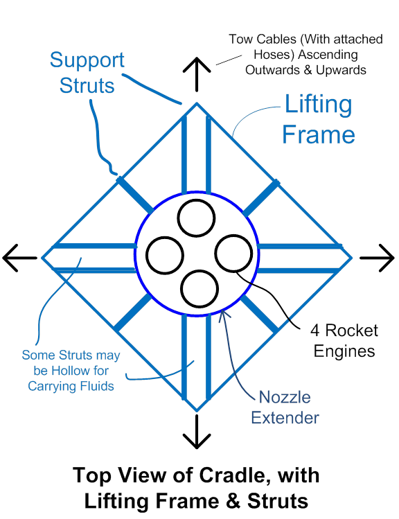
Figure 22 (above)
Only one major element of the design needs to be
described in detail, and that is the matter of injecting the added reaction
fluids into the combustion chamber. It
is possible that the feed hoses could be constructed to resist (carry)
high-enough pressures that the pressurized fluids would be highly-enough
pressurized to be shot straight into the combustion chamber without
assistance. However, such extremely-high
pressure hoses might present safety (rupture) hazards, and might be so heavy as
to impede the whole assist mechanism. We
assume here that safety and efficiency considerations require a boost pump to
inject the fluids, permitting relatively lower-pressurized, lighter-weight
hoses. It might even be wise to have
separate boost pumps for air and water on the one hand, v/s JP4 (with a bit of
“parasitical” safety nitrogen gas intermingled with it, as mentioned before) on
the other hand. However, note that it is
common practice to intermingle an oxidizer and an oxidant, in a high-pressure,
high-flow-rate environment, such as the pre-mixer right before the tip of an
oxy-acetylene torch, for example. If
premature combustion sets in, it is rapidly “shown the door”,
bar-room bouncer-style, by the high speeds of the fluid flow, and is promptly
spat out into the main combustion chamber (the torch’s external flame in the
welder’s case). So here, all fluids will
meet, right as they feed a rigid-walled, rotating-helical-screw-turbine-style
injector pump, which force-feeds the fluids into the combustion chamber.
Two designs are shown here, each of which powers the
injector turbo-pump with rotational energy derived from a small jet
engine. Once again, JP4 is available
throughout the system, as is ambient air, so why not? JP4 has excellent energy density.
The first scheme shown will be to bury the turbo-pump
into the walls of the nozzle extenders.
A clear advantage here is that there need not be ANY injection point
modification of the original nozzle walls of the original rocket (the part that
ascends after demating with the assisting, extended
nozzle). Conversely, a clear
disadvantage is that a belt or chain is needed to transfer rotational energy
from the small jet engine to the turbo-pump.
This is an added point of possible failure. The drawings here below show only the outer
wall of the combustion chamber.
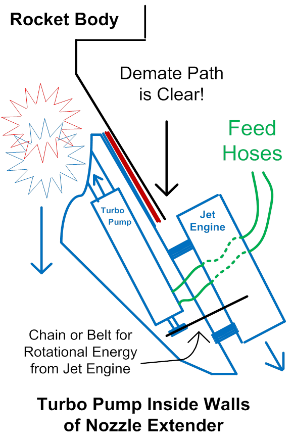
Figure 23 (above)
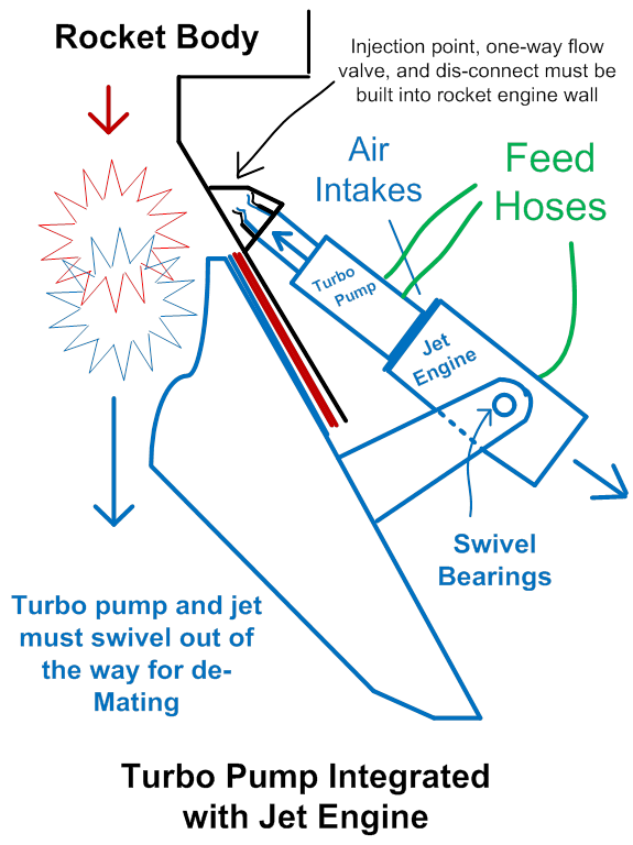
The second scheme shown will be eliminate the belt or chain, which reduces complexity and points of failure. Also, the turbo-pump is more accessibly for maintenance or replacement. The turbo-pump here is mounted on the rotating central shaft of the jet engine, and the entire assembly can swivel or pivot to clear the path for the demate process. The price is, the nozzle walls (of the true rocket, not the assisting assembly) must be modified to create a pressure-fitted injection point, which is also a point of failure. De-mating it may create a bit of downwards, parasitical drag on the rocket, lasting only for the de-mating time period. An inherent one-way flow valve must be built in so as to not spill rocket exhaust after demating. Think of the safety relief decoupling mechanism built into the gasoline hoses at the gas station…
The above-described schemes leave some major, expensive elements
exposed to the rocket’s exhaust during the demating,
which may be an un-acceptable. Even yet
another scenario might embed a contiguous, integrated, in-line jet engine and
turbo pump as shown in the second of the 2 above drawings (no belt or chain),
with the entire assembly buried into the walls of the rocket nozzle
extension. This might not all fit very
well, and breathing external air would become a little more troublesome for the
jet (or it would have to parasitize the main rocket engine’s combustion chamber
for pressurized gasses to drive the turbine, which is certainly a viable
choice). But such scenarios are
certainly possible (and would eliminate both failure
points, the injection point and the belt or chain). And it would shield expensive system elements
from the exhaust of the rocket during demating. So, all told, this third (un-illustrated)
choice may actually be best. If room
(space) is an issue, especially vertical space in the nozzle extender, then
more, smaller turbo-pumps, not fewer large ones, can be used.
This concludes the summary descriptions for the major
elements of the jet-assisted vertical “sling shot” for assisting rocket
launches.
Detailed
Discussions of Principles, Trade-Offs, and Alternatives
Now
that the basic, primary elements of the proposed design have been described,
let’s move off to show a minimal amount of math, or at
least numbers, to show that this idea is both practical and effective. Then let’s go over principles, trade-offs,
and alternatives or variations of this design.
First, what kinds of speeds can we expect at various points in
time and in elevations off of the launch pad?
http://en.wikipedia.org/wiki/Thrust-to-weight_ratio shows the space shuttle as having, at take-off, a mere
1.5 for thrust-to-weight ratio, which also means the astronauts feel 1.5 “Gees”
(acceleration force as a multiple of Earth’s gravity at sea level). The launch-assist method here described
assumes 2 “Gees” of acceleration… Too
much would mean that the rocket would be travelling too fast, by the top of the
1,200 foot assist towers, for the injectors to be timed well enough to do their
job. Too slow would mean the assist
scheme is not doing its job well enough to achieve its goals (increase payload
and/or reduce fuel and vehicle mass of the rocket itself). 2 “Gees” may or may not be the optimal target
number, but it is probably close, and can show that resulting numbers are
realistic. The question of, how fast do
you “fall into the sky” at 2 Gees, one Gee being cancelled out by Earth’s
gravity, is exactly the same as the question of, how fast does an object fall
in Earth’s gravity? http://answers.yahoo.com/question/index?qid=20090624115259AA3RuYH shows how to use calculus to derive time for
a given distance. The rest of the math
is elementary. Because this author is
lazy, the exact correct “G” for Earth, at 32.2 feet/second-squared is rounded
down to just 32 for calculating the below table… So our assisted rocket is going to pull very
slightly less than 2 “Gees” off of the launch pad. The below table shows
distance, time, and speed above the launch pad.
12
feet - 0.87 secs, 28 ft/sec, 19 mph
25
feet - 1.25 secs, 40 ft/sec, 27 mph
50
feet - 1.8 secs, 58 ft/sec, 40 mph
100
feet – 2.5 secs, 80 ft/sec,
54 mph
200
feet – 3.5 secs, 112 ft/sec, 76 mph
300
feet – 4.3 secs, 138 ft/sec, 87 mph
400
feet – 5.0 secs, 160
ft/sec, 94 mph
500
feet – 5.6 secs, 179
ft/sec, 122 mph
600
feet – 6.1 secs, 195
ft/sec, 133 mph
700
feet – 6.6 secs, 211
ft/sec, 144 mph
800
feet – 7.1 secs, 227
ft/sec, 155 mph
900
feet – 7.5 secs, 240
ft/sec, 164 mph
1,000
feet – 7.9 secs, 253
ft/sec, 173 mph
1,100
feet – 8.3
secs, 266 ft/sec, 181 mph
1,200
feet – 8.7
secs, 278 ft/sec, 190 mph
1,300
feet – 9.0
secs, 288 ft/sec, 196 mph
1,400
feet – 9.4
secs, 301 ft/sec, 205 mph
1,500
feet – 9.7
secs, 310 ft/sec, 211 mph
So then a nine-second assisted burn
time, and 2 “Gees”, and 1,200 foot tall launch-assist towers sound like good
numbers. The towers are not so tall as
to be impractical, and the injectors embedded in the rails should still be able
to “keep up”.
Now, what about the amount of fuel
sitting in the rocket, at launch, that can be saved by the assisted-launch
scheme? For this, we consult http://en.wikipedia.org/wiki/Rocket and search for the below out-take:
Begin Wiki quote:
Main article: Tsiolkovsky rocket equation
The delta-v capacity of a rocket is the theoretical total change in velocity that a
rocket can achieve without any external interference (without air drag or
gravity or other forces).
When ![]() is constant, the delta-v that a rocket vehicle can provide can be
calculated from the Tsiolkovsky rocket equation:[103]
is constant, the delta-v that a rocket vehicle can provide can be
calculated from the Tsiolkovsky rocket equation:[103]
![]()
where:
![]() is the initial total mass, including propellant, in kg (or lb)
is the initial total mass, including propellant, in kg (or lb)
![]() is the final total mass in kg (or lb)
is the final total mass in kg (or lb)
![]() is the effective exhaust velocity in m/s or (ft/s)
is the effective exhaust velocity in m/s or (ft/s)
![]() is the delta-v in m/s (or ft/s)
is the delta-v in m/s (or ft/s)
End Wiki quote.
From the preceding table we chose a
9-second burn, but
that’s with the Earth’s gravity negating 1 of the 2 Gees being pulled. Now re-calculate and see what our delta-V
would be if Earth’s G was not there, so we can see what Tsiolkovsky
rocket equation has to say…
Use 64 ft/second-squared here, rounding off again… This below table shows a launch profile of a
rocket lifting off of the Earth at 2 “Gees” of acceleration, if the Earth had
no gravity… Alternately, in the real
world, it shows a rocket lifting off at 3 “Gees”. This is done so that we can see what our
speed is after a 9-second burn (our “delta V” at 2 “Gees” in the real world,
with the rocket having to burn enough fuel to counter-act the Earth’s one “G”;
in other words, we are correcting the rocket equation, which excludes gravity,
to include gravity). The whole table is
shown just to give the reader another look at how the numbers stack up at a
higher rate of acceleration. The real
purpose is to get the 576 ft/sec “delta V”, which is what we’d have after the
9-second, 2-Gee burn if Earth’s gravity is taken out.
100
feet – 1.8
secs, 115 ft/sec
400
feet – 3.5
secs, 224 ft/sec
800
feet – 5.0
secs, 320 ft/sec
1,200
feet – 6.1
secs, 390 ft/sec
1,600
feet – 7.1
secs, 454 ft/sec
2,000
feet – 7.9
secs, 506 ft/sec
2,500
feet – 8.8
secs, 563 ft/sec
2,600
feet - 9.0 secs, 576 ft/sec ***
2,700
feet – 9.2
secs, 589 ft/sec
Use 576
ft/sec for “delta V”, then. For the
rocket’s exhaust velocity, “Wiki” ( http://en.wikipedia.org/wiki/Specific_impulse
) tells us that says a bi-propellant exhaust velocity for example is on the
order of 4,400 meters per second! 4,400
times 3.28 feet/meter is 14,432 ft/sec. ( 576 ft/sec ) / ( 14,432 ft/sec )
= 0.04 … Now the “Ln” in the
equation means natural log, and just iteratively plugging some numbers in there
and taking natural logs to solve the equation, M0 / M1 (initial mass over final
mass after the burn) comes out to ln(1.04 / 1) = 0.04 … Only 4% of your (including fuel) mass is
blasted away in the first 9 seconds of burn.
Admittedly in the assisted-launch scenario, SOME of the initial mass of
rocket fuel sitting in the rocket (proper), on the launch pad, pre-launch, is
going to have to be burned to get the temperature up (in the secondary
combustion chamber or in the combined combustion chamber), in order to ignite
the JP4. This amount of fuel can easily
be counter-balanced (or exceeded) by the additional thrust (lift force)
conveyed to the rocket through the JETs and cables. And we didn’t calculate for air resistance
either… These calculations are quite
rough, and are merely intended to show that the percentage of launch-weight
fuel that is expended in the first few seconds off of the launch pad, is NOT horribly significant, if we pull only 2
“Gees”. The assisted-launch scheme,
then, is not horribly gainful if we limit ourselves to pulling 2 “Gees” for
human-passenger comfort and safety (and the assist towers are limited to 1,200
feet or so). Parenthetically, NOTE that
if advances are made in materials sciences that permit the economical
construction of much taller towers, then suddenly the ideas here described,
will become MUCH more attractive!
Note also that if we go back to “Wiki” and re-run the
numbers, not for a “bi-propellant” fuel (like in the old Apollo/Saturn 5 days), but
for a solid-rocket fuel (as in PART of the space shuttle scheme), then the
exhaust velocities are significantly lower.
Solid rocket fuel then… 2,500 meters per second, 2,500 times
3.28 feet/meter is 8,200 ft/sec. ( 576 ft/sec ) / ( 8,200 ft/sec )
= 0.07 … Iteratively solve again and ln(1.073/1) is
0.07, so our assist scheme, pulling 2 “Gees” for 1,200 feet (9 second burn),
would save us about 7.3% of initial launch weight. Space shuttle being a blend of dual liquid
fuels and solid fuels, halfway between 4% and 7% is maybe 5.5% or so… That is what we could expect to save in the
scheme so far described, for a new, modern launch system. Still not that great.
However, if we pull much higher “Gee” forces for
launching robust cargo (excluding humans), then perhaps the capital costs for
initially building the launch-assist scheme can be paid off that way. Then we can still use the same scheme for
launching humans, as a smaller side benefit.
Suppose we pull 10 “Gees”, meaning that we “fall into the sky” at 9
“Gees” (take out Earth’s gravity, of course).
We will be travelling MUCH faster by the time we get to the tips of the
towers, and it is questionable if the propellant injectors will be able to keep
up. In this scenario, perhaps it would
be best for the JET assemblies to stop sipping fuel, and rely on reserve tanks
only, and to rely on the tow cables more heavily, to get the “bang for the
buck”, at the upper reaches of the towers.
So for reference, here are the numbers, re-crunched for
“falling into the sky” at 9 “Gees” or pulling 10 G-forces (for those
mathematics masochists intent on re-creating my numbers, I used 32.2
ft/sec-squared this time, times 9 is 290, 290 / 2 = 145 for the square root of
distance / 145. Then take time *
multiply by 32.2 * 9 = 290 =
to get speed, 5,280 feet per mile, 60 secs * 60 minutes… * ( 60 * 60) / 5,280 = *0.68 ) :
12
feet - 0.29 secs, 84.1 ft/sec, 57 mph
25
feet - 0.42 secs, 121.8 ft/sec, 83 mph
50
feet - 0.59 secs, 171 ft/sec, 116 mph
100
feet – 0.83
secs, 241 ft/sec, 164 mph
200
feet – 1.17 secs, 339 ft/sec,
231 mph
300
feet – 1.44
secs, 418 ft/sec, 284 mph
400
feet – 1.66
secs, 481 ft/sec, 327 mph
500
feet – 1.86
secs, 539 ft/sec, 367 mph
600
feet – 2.03
secs, 589 ft/sec, 401 mph
700
feet – 2.20
secs, 638 ft/sec, 434 mph
800 feet
– 2.35
secs, 682 ft/sec, 464 mph
900
feet – 2.49
secs, 722 ft/sec, 491 mph
1,000
feet – 2.63
secs, 763 ft/sec, 519 mph
1,100
feet – 2.75
secs, 798 ft/sec, 543 mph
1,200
feet – 2.88
secs, 835 ft/sec, 568 mph
1,300
feet – 2.99
secs, 867 ft/sec, 590 mph ***
1,400
feet – 3.11
secs, 901 ft/sec, 613 mph
1,500
feet – 3.22
secs, 934 ft/sec, 635 mph
Call it a 3-second burn for
launch-assist towers 1,300 feet tall then.
Reactant injectors (rail embedded)
may or may not be able to keep up any more, at these speeds (this is an
engineering question, not a science or mathematics question). But for the sake of getting some more numbers
for analysis, let’s continue. In order
to solve the “rocket equation” for how much fuel we’d save pulling ten “Gees”,
we have to correct for gravity, and see, what is our speed if Earth’s gravity
isn’t there, and we are pulling 11 “Gees” instead. 11 * 32.2 = 354, 354 / 2 = 177 …
1,000
feet – 2.38
secs, 843 ft/sec
1,100
feet – 2.49
secs, 881 ft/sec
1,200
feet – 2.60 secs, 920 ft/sec
1,300
feet – 2.71 secs, 959 ft/sec
1,400
feet – 2.81 secs, 995 ft/sec
1,500
feet – 2.91 secs, 1,030 ft/sec
1,600
feet – 3.01 secs, 1,066 ft/sec ***
1,700
feet – 3.10 secs, 1,097 ft/sec
Oooops,
confession, I corrected for the Earth’s gravity TWICE above, I should have used
10 “Gees” not 11 “Gees”… I was just
testing you, Dear Reader! The numbers
are close enough, though; I won’t re-run them.
1,066 ft/second then is a good number to throw into the
“rocket equation” to get a good idea of what we might save with a 1,300 foot
tall assist tower, and pulling 10 or 11 “Gees” for 3 seconds. Run the numbers only once this time, use
exhaust velocity halfway between a bi-propellant and a solid fuel (approximate
a modern, shuttle-like setup). Halfway
between 2,500 m/s (solid) and 4,400 m/s (bi-propellant) is (
2,500 + 4,400 ) / 2 = 3,450… Times 3.28 feet/meter
= 11,316 ft/sec. ( 1,066
ft/sec ) / ( 11,316 ft/sec )
= 0.094 … Iteratively solve again and ln(1.1/1) is
0.095, we are now saving about 10% of our launch weight with the assist
scheme. Still not
stellar… BUT, what if us getting
up to a speed of 190 mph (pulling 2 Gees) or 590 mph (pulling 10 Gees) before
we clear the tower tops, or some halfway point between these 2 numbers… What if this allows a new type of rocket or
jet or rocket/jet hybrid to go into operation at that point? Save that thought for later!
Before delving back into details of
the assisted-launch scheme, a few words about basic principles seem to be
warranted. http://en.wikipedia.org/wiki/Rocket and then specifically the drawing at http://upload.wikimedia.org/wikipedia/commons/4/47/Rocket_nozzle_expansion.svg are
very instructive. Everyone knows that
rockets propel themselves by “throwing mass out their rear ends” just like a
motor-boat and water, or an airplane and air.
So that explains the need for a combustion chamber (almost entirely
enclosed, often, to maintain temperatures and compression to sustain
combustion) with a hole (“throat” of constriction) for “throwing mass out your
$#%#”, if you will. But
what about the flaring nozzle?
Why is it needed? Because
additional thrust can be obtained by the pressures of the escaping hot
gasses. If the hot gasses behind or below
the nozzle are more highly pressurized than the ambient air (or vacuum, vacuum
being very thin gas, actually), then they “push” against the nozzle wall,
imparting more thrust to the rocket.
Rockets
launched from sea level or anywhere in the lower atmosphere, have rocket
nozzles that are “grossly over-expanded”, meaning they are much larger than
they need to be, for working in the lower atmosphere. Their hot gasses cool down fast enough that a
lot of the nozzle “goes to waste”, and is extra mass carried without benefit in
the lower atmosphere. Only at higher
elevations, in thinner air, do the hot gasses (at the tail end of the nozzle)
finally, clearly exceed the pressure of the atmosphere, so that even the tail
end of the nozzle is giving additional thrust to the rocket. In the near-perfect vacuum of space, finally,
the “air pressure” is near nothing, and so there, one might want a 50-foot long
nozzle to capture ALL the benefit of the pressure differentials, at the logical
extreme. There, our nozzle is
“under-expanded”, then, in the interests, of course, of saving mass in that
nozzle.
The
launch-assist scheme can “solve” this problem, at least for the first 1,200
feet of launch. Air pressure
differentials across 1,200 feet are minimal, so the extended nozzles can be fairly
accurately tailored to be exactly what they need to be, for the first phase of
launch.
The
“Lifting Frame” Part of the “Cradle”, and Trade-Offs There
Bouncing
around to a few topics in more detail, concerning the assisted-launch scheme,
there is the “cradle” and “lifting frame”, for example. Why bother with the lifting frame (and struts
from there to the nozzle extenders as well) at all? Why not send the lift cables and hoses
straight on down to the nozzle extenders, dispensing with all the rest, in
order to save mass? Well, two reasons:
‘1) By adding the lifting frame, the
lifting frame materials can specialize in being optimally light-weight, yet
being resistant to the high tension (“pulling-apart”) forces that they will
have to withstand. The lifting frame
could perhaps even be primarily made of very thick, low-flexibility
cables. By un-burdening the nozzle
expanders from having to withstand the high tension forces of the lift cables,
the nozzle expander design can concentrate on specializing to do its job, and
let the lifting frame specialize in doing its job, with perhaps less mass
overall. ‘2) Stability and control. We don’t want the rocket to topple over. Where the tow cables meet the lifting frame
is where the control point is. In fact,
there is a trade-off there as well. The
below drawing shows, in series, no lifting frame at all, v/s a deeper and
deeper “basket” or “cradle” (longer and longer struts). Imagine the JET assemblies controlling (via
controlled thrust and via brakes) the tilt of the cradle plus rocket, and
trying to keep the rocket correctly balanced.
Too-shallow of a cradle (or no cradle) invites instability, and too-deep
of a cradle loses efficiency, in that more and more of the height of the
launch-assist towers goes to waste. The
optimal balance must be found as the JET assemblies “rock the cradle”! The rocket’s center of mass is shown as a red
dot. Ideally the center of mass stays
low for stability. Blue
arrows shows the tilt-control or swiveling-forces focus. More stability
means not only more wasted vertical capacity of the assist scheme, but also
increased weight in the struts. The
proper compromise must be found and implemented.
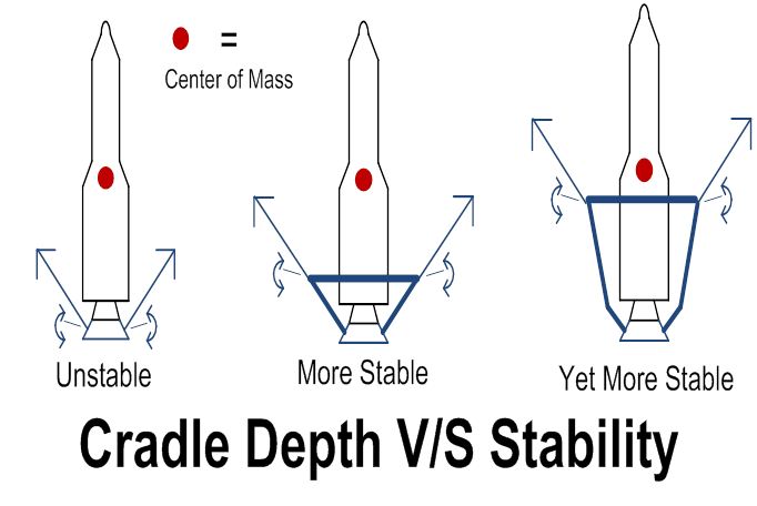
Figure 25 (above)
The
“Struts” Part of the “Cradle”
Adding
the lifting frame is also a good idea because now we can add struts as
well. The struts can largely be made out
of, or contain, shock absorbers (gas-pressure-filled and/or
spring-loaded). These will help isolate
the nozzle extenders to rocket nozzles interface from shock and
vibrations. Struts (as well as the
lifting frame) could be hollow to accommodate propellant flow if desired (even
hollow shock absorbers can be designed for this). On the “Rube Goldberg” side of things
(probably not practical, for high-speed fluid-flow needed here), hollow shock
absorbers could be designed with one-way valves such that mechanical energy
absorbed by the shock absorbers, could help propel the conducted fluids. Also somewhat obvious but deserving mention,
the swivel point (swivel bearings) for the assembly of small jet engine plus
turbo-pump shown in Figure 24 could be part of a strut (for structural mass
conservation). The strut could become a
2-pronged fork before it hits the nozzle extenders, allowing the space between
the 2 prongs to accommodate the turbo-pump.
Discussion
of Control Scheme Variables and Options V/S Number of Rocket Engines, Etc.
Conventional
rocket launches today allow the rocket engines to swivel. This allows great power and flexibility to
the control system. In the event of a
large upset in stability, thrust re-direction can over-correct for it and then recover. In a maneuver that is familiar to car drivers
who have driven on icy roads, the back end must follow the front end to execute
a recovery. A simple set of drawings
should suffice to illustrate the idea:
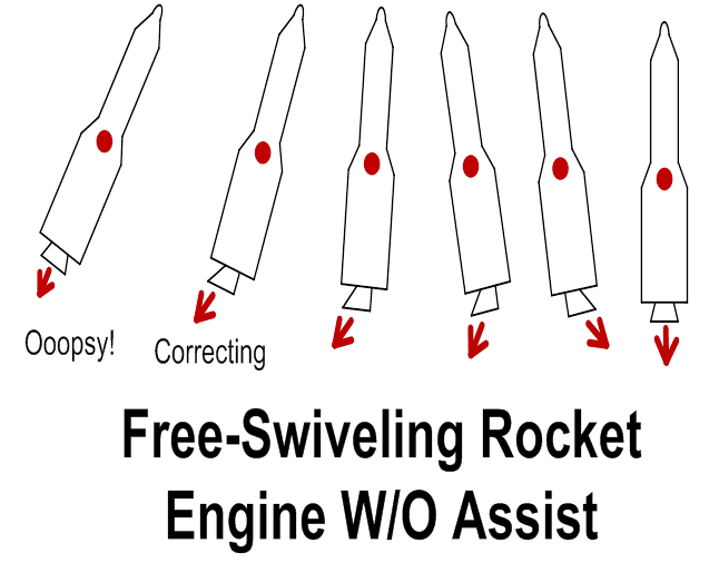
Figure 26 (above)
During
the assisted-launch phase, the free-swiveling rocket engine can only be used as
part of the control scheme in very limited circumstances. One scheme would be with only TWO
launch-assist towers, and the rocket and cradle
“walking the tightrope” between the two.
In this case, the free-swiveling rocket engine(s) would only have a
freedom of motion perpendicular to the “tightrope”, and the brakes v/s thrust on
the JET assemblies would have to complete the control equations. If there were more than one rocket engine,
they would all have to be in-line (centered on the “tightrope”) for this scheme
to work. This whole idea seems at least
slightly preposterous, but not entirely prohibited, so it does not deserve a
drawing. Also preposterous (MORE
preposterous that is, but once again not prohibited by laws of physics) would
be to have the rocket engines not only be swivel-able, but also be on
telescoping members with respect to the main rocket body, so that a rigid,
unified nozzle extender could mate, in three dimensions, to multiple rocket
nozzles, three-dimensionally arrayed, swiveling and telescoping at once, so
that the outermost “lips” of their nozzles remain in one plane (which plane
mates to the unified nozzles extender).
This is not plausible in engineering terms, but is mentioned in an
academic vein, in the name of completeness…
This is the only way (other than the afore-mentioned tightrope scheme)
that multiple swiveling nozzles can accommodate the assisted lift scheme
envisioned here. So what this means is,
the control scheme for the assisted-lift technique MUST prevent wild gyrations
in configuration… It will not be as
robust a control scheme as is the case with a free-flying rocket. Realistically, during assisted-lift launch
phase, the thrust and the brakes of the JET assemblies will have to be in
control.
What
must be prevented, is any scenario in which the center of gravity of the rocket
exceeds (or realistically, even gets close to) the swivel points where the lift
cables meet the cradle. Since the lift
cables come in at a 45 degree angle, the cable lift forces have both an “X” and
a “Y” component. If the JET assembly
creates more thrust (or takes pressure off of its brakes) to create more mixed
“X” (horizontal) and “Y” (vertical)
forces, it is going to create more “X” force, in a manner in which is going to
help the situation, whether or not the “tipping point” has been exceeded. That is, the opposite lift tower and its tow
cable, which has to drop back or slow down, is going to have to “give some
slack”, which causes the “X” or “pull-on” force of the pulling-harder lift
assembly to help the situation. But the
increased “Y” pull, post-tipping-point, is going to aggravate the
situation! It risks having the rocket
topple or break, that is. A drawing
should hopefully clear up the concepts:
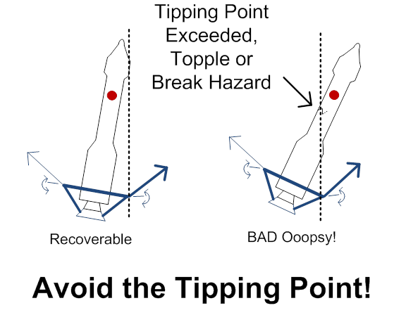
Figure 27 (above)
The
above drawing should also be interpreted to say, the rockets designed to use
the assisted-lift technique should be designed with a low center of
gravity. Also one could conclude that a
wider top opening of the cradle leads to more stability (albeit at the costs of
a more massive cradle). Precision, quick
control (primarily with fast-reacting brakes between the JET assemblies and the
launch-assist towers) will be vitally essential. The launch towers must be widely enough
spaced to allow “slack” in the tow cables, for the control scheme to work. Alternately put, the rocket-plus-cradle
assembly must have some freedom to travel North-South, East-West, without
banging into a tower, during the 1,200 feet of assisted lift, for the control
scheme to work.
The
following ideas are probably not practical, or needed, in terms of costs and
extra mass, but are included in the name of academic completeness: ‘1) If
the cradle is deep enough, swiveling mechanical members (that swivel upwards
out of the way when the rocket departs the cable) could be mounted on the lift
frame, so as to go out and touch the rocket, during assisted lift phase, to
prevent toppling, and ‘2) the rocket itself could include, towards its top,
thrusters pointed in different directions in order to combat toppling.
As
mentioned, two lift towers is theoretically possible, but likely not
plausible. Three is better, but 4 is probably best.
More than 4 gets complex, and provides more opportunities for an
accident to cripple or destroy the towers. More towers make for more targets for
accidents, that is.
“Flying
Off of the Rails” is Indeed Hazardous!
Somewhat
haphazardly bouncing from topic to topic, one of the very most serious
potential weak spots in this entire scenario is what happens at the end of the
assisted-lift phase. If not alleviated,
the hazards at the tops of the towers are very serious. If the JET assemblies do NOT fly off of the
tops of the buildings, then they must brake to a stop at the tops of their
journeys, wasting much of the building’s costs (that do not add extra lift, at
the tops of the towers). Also, the
cradle assembly will continue upwards, yanking upwards at the JET assemblies at
the end of the journey, as well.
Academic completeness time again:
If the braking method is used, and the JET assemblies start to brake
well enough ahead of time to kill the entire upwards velocity of the cradle
assembly, then yet more vertical capacity of the towers goes to waste. If the entire velocity of the cradle assembly
is NOT killed by the time the JET assemblies reach full-stop at or near the
tower tops, then, due to momentum, it will travel upwards to the point where
(up past the JET assemblies and tower tops, inverting the 45-degree cable angle
momentarily) it will forcefully yank inwards towards the launch site at the
center, on all of the buildings, via the now-inverted cables. The buildings must then be built strong
enough to resist that cables-snap action.
Perhaps with horizontal cross-members between the building
tops? That would be hard to accomplish
if the buildings are sufficiently widely separated, and these cross-members
would also provide more targets for accidents (think falling or exploding
rocket). Travelling now clearly into
“Rube Goldberg” territory, the cross-members, if used, could be equipped with
explosive bolts for self-destruction if they come into danger, and there is
sufficient warning time. The cross-bars
can be sacrificed to prevent the towers from coming down with them, that is, in
the face of impending disaster. If
going-astray rockets can be rigged to self-destruct on command (as they often
are), then so can segments of launch-assist towers..
Suffice
it to say, then, that having the JET assemblies fly clear off of the tops of
the towers seems to be a good choice.
This does, however, present its own set of challenges: What happens when the JET assemblies fly off
the ends of the rails? For most of the
upwards journey, the forces of the jet engines are counter-balanced by the
cables from the “harp towers”, as the reader will recall. And co-planarity of the JET assembly with the
plane of the vertical rail is enforced by the (reasonably) tight-fitting mating
surfaces between the rail and the JET assembly’s fuselage, and by the rollers
on that fuselage.
But
what happens during the fractions of a second when the JET assembly fuselage is
half on the rails, half off of the rails?
During this time, twisting or torsional forces threaten to wreak havoc
on the rail and on the JET assembly (co-planarity enforcement is lost). So what needs to be done is: ‘1) Towards the last legs of the upwards journey,
the rail’s injectors must start (on the JP4 side) to inject either nothing
(depending on the JET assembly to release nitrogen into its intake and funnel
area to purge JP4), or to inject, from the rails, nothing but pressurized
nitrogen to accomplish a “purge” of most JP4, so that there won’t be much of a
JP4 spill when the JET assembly flies off of the rail, ‘2) At the tail end of
the upwards journey, the jet engines must be swiveled to provide thrust that is
slightly to moderately greater than the pulling forces of the tow cables, and
with the thrust also aligned to be parallel to the tow cables (previously to
that they have been mostly vertically oriented in order to deliver maximum
vertical towing forces), ‘3) The tower’s brake pads must give way to rollers
instead, after the rail stops, so that the JET assembly, with thrust slightly
greater than the pull forces of the tow cables, can “roll” right up the building
side for a little while, and ‘4) then finally we REALLY come to the final demate. The JET
assemblies could cut down their thrust so as to stop rolling up the side of the
building, pulling slowly away. That is
least traumatic, but a jet cannot change it thrust very rapidly. So that means more vertical building space to
waste. A compromise is to deliberately
throw in a “sacrificial crunch area” (think barrels along the highway, in front
of concrete wall abutments) at the top of the building, which would need to be
replaced after each flight operation.
The “crunch are” absorbs the extra “push force” with which the JET
assembly is still pushing into the building, post-demate
from the rail.
OK,
that latter crunch-barrels idea is possible and is retained (once again) for
academic completeness. If this author
was to be accused of “making things up as he goes alone”, he would be forced to
confess! The clearly better alternative
(requiring far less maintenance or replacements) here for smoothing the
transition of the JET assembly off of the launch-assist tower-top is this:
Place a large tapering-back hinged plane at the top of the tower, and put large
spring-loaded or gas-pressure-filled shock absorbers to the rear of the hinged
plane (with rollers). Now the trauma
(risk of sudden uncontrolled motions) is taken out of the departure of the JET
assembly off of the top of the building.
Here are some drawings to illustrate:
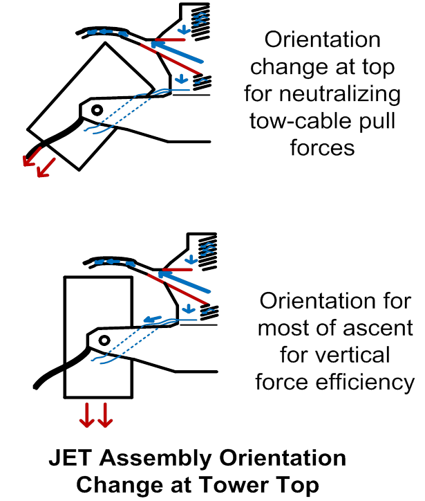
Figure 28 (above)
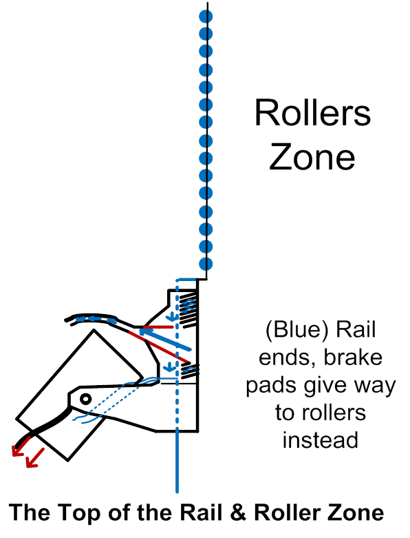
Figure
29 (above)
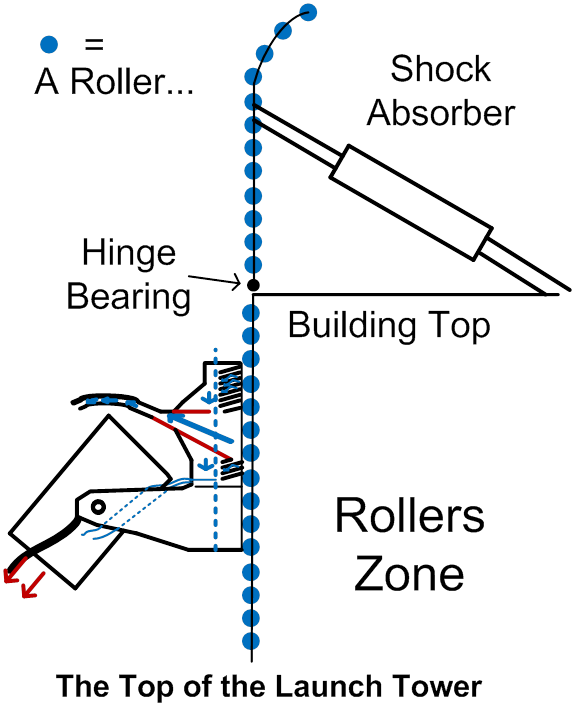
Figure
30 (above)
More
Details About the JET Assemblies
The
JET assemblies may or may not need to include a swivel motor inside the
“fuselage”, see
Figure 12. If the
jet engines themselves have sufficiently quick-reacting and powerful thrust vectoring
embedded in them, this swivel motor will not be needed. This author knows next to nothing special
about embedded thrust vectoring inside jet engines. The JET assemblies will probably NOT need
very large (or perhaps even, any at all) airflow-directing fins or wings as are
shown in drawings here (but they look cool, right?). Since they will never travel at exceedingly
great speeds, and since they will land slowly, vertically, after a short trip,
the air-flow control can be minimal to non-existent, most likely. Their journeys, post-building-tops, will
likely be very short. A
probably-non-preferred alternate scenario is for them to carry enough jet fuel
to continue their rocket-assisting duties (feeding the rockets more auxiliary
reaction mass) well past the building tops.
Since they must continue (in the post-building-top mode) by burning and
providing self-carried fuel, AND since their thrust must be directed at an
angle to maintain separation distance from the rocket, this scenario is
possible but not plausible.
It is
true that in the above-described scenario, the JET’s brakes are lost at the top
tip of the launch tower. There goes a
major fraction of your launch-control system!
But before this happens, the rocket (proper) should fully power its
engines (increase self-carried fuel-feed rate to normal), and lift up out of
the cradle, assuming its own, normal, self-sufficient control scheme.
One
alternative design for the JET involves more than two
funnel-and-deflection-louvers (fluid receptacle) assemblies. This could be done with or without changing
the basic shape of the rail. Suppose,
for instance, that we wanted to separate JP4 v/s air v/s water. Instead of 2 flat faces to the rail, we could
have 3 flat faces. OR, we could retain
the 2-flat-faces design as has always been shown here. In either case, we could make room for 3
separate columns of injectors inside the rail, and 3 separate fluid-receptacle
assemblies inside the JET. The
importance of near-perfectly sealing some such fluid receptacle compartments
v/s another will vary. Separating air
from JP4, for example, will be more important than separating air v/s water.
For
now, this is all of the additional comments about the JET assemblies.
More
Details About the Nozzle Extenders
A few
more comments about the nozzle extenders may be in order. Comments were made, earlier, about truncating
or omitting walls between one nozzle extender and another (fusing them together
into one giant nozzle extender, with only the outermost nozzle walls being very
long, reaching down to the ground for structural support pre-launch, and
containing the hot gasses till the hot gasses are optimally expanded, deriving
additional thrust). Another way to say
this is, if adjacent streams of pressurized gasses press against each other,
the hot gasses are providing, from one stream to another, the internal “nozzle
walls” there… Throwing in an internal
nozzle wall, with high pressures on both sides, does not allow for a pressure
differential to push the rocket upwards...
The additional mass carried, for the internal inter-hot-gasses-streams,
goes to waste. This is NOT true, though,
if there is a large gap in between semi-adjacent nozzles on the rocket
proper. This can be illustrated with two
more drawings that are oriented towards showing an alternative scheme for
applying the assisted-lift technique, and that is what might be called the
“doughnut-shaped” or toroid-type nozzle extender. This goes towards solving the “plumbing
problem” of providing supplemental reaction mass to multiples of rocket
engines. The rocket (proper) in this
case, has engines directly slightly outwards, around the bottom, with NO
engines in the center. The nozzle extender will then have an inner wall for
weight bearing (pre-launch) and an outer wall, which may or may not bother to
extend far enough to reach the ground.
If the outer walls are extended far enough to reach the ground,
“over-expanded” they may then be, yes, but…
There may be an advantage in doing that, for making room for turbo-pumps
mounted entirely inside the nozzle walls, as previously mentioned.
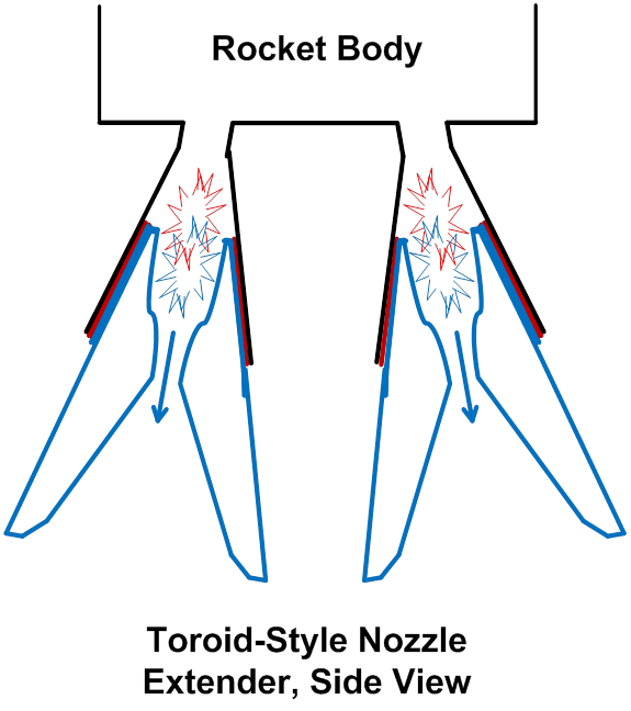
Figure
31 (above)
In the
toroid scheme, complete nozzle-extender walls are needed in a “doughnut shape”
(heavy multiple blue lines below, inner and outer walls), but there will be NO
need, inside the doughnut, for vertical walls between one stream of hot gasses,
and another, which is immediately adjacent (travelling in a circle around the
donut). The top view should clarify this
idea:
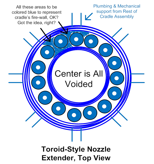
Figure
32 (above)
In
other words, referring back to Figure 21, the toroid scheme solves a potential problem with
what was discussed earlier surrounding figure 21… The innermost rocket engines in figure 21, cannot get “plumbing” for additional reaction mass, very
easily. If the (un-supplemented) innermost
rocket engines are NOT putting out enough high-pressure gasses, the inner
“doughnut wall” as shown above, may be needed, to extract more thrust (via
gas-pressure differentials), even in the case of figure 21. By arraying all rocket engines out along the
periphery, and using the “doughnut approach”, all rocket engines can easily get
additional reaction mass, and the gas-pressure differentials are optimally used
for thrust. The “firewall” above isn’t
really so much needed as a firewall, in the case above, it is more-so the
structural material that holds the entire super-assembly of unified nozzles
extender, together. The so-called “firewall” obviously needs to be placed below
(or at the point) where the rocket-proper’s bottom tips of nozzles touch the nozzle
extender.
Another
set of options (concerning nozzle extenders) that needs to be explored is one
that also involves propellant fluids.
The primary design described how JP4, compressed air, and water would
all be thrown into the secondary combustion chamber in some rocket designs, or into the combined primary/secondary combustion
chamber in those (typically liquid hydrogen and liquid oxygen) rocket engines
where the combustion chamber and nozzle are one and the same. However (especially if the amounts of water
involved are large), then injecting water at this point would dampen the fires
too much. This author is not smart
enough to spell out the trade-offs and pick the right choice here (amounts of
water and where to inject), but the previously-designed design may be
optimal. If it is not, if the extra
masses and complexities to be added to the nozzle extenders are worth it (to
use more water, for example, w/o damping the fires), then several other options
are available.
First,
simplest, and easiest, is simply to inject the compressed air and JP4 in the
added-on combustion chamber, without significant amounts of water. Then inject the water in the added-on nozzle
or expansion area, with separate turbo-pumps.
Call it the “water after-burner”, if you will, although of course the
water “merely” turns to steam, it doesn’t burn.
It DOES expand as it turns to steam, though, adding a great deal of
thrust! Now the water does NOT dampen
the fires. Water and air could be
separately handled all the way from the tower, through the JETs and hoses, to
the cradle. The extra complexity is
probably not worth it. Near-perfection
of separating air v/s water is not needed.
Instead, the better alternate here would be, at the nozzles extender
area, to add a liquid-gas separator.
This has previously been described in terms of separating an inert gas
from JP4, but here again is a similar summary:
A tank
would allow gravity/acceleration and spin separation between the air and water,
with the air being drawn (most of it at least) off of the top of the tank. This tank should ideally be funnel-shaped,
with the fast-flowing air-water mix directed downwards in a spiraling motion
along the sides of the funnel; small funnel end down, large funnel end up,
air-bleed outlet to the top middle of the funnel.
If the
use of exceeding large amount of water is actually the most cost-effective
here, and the amount of pressure and heat in the extended nozzle area is not sufficient
to flash all the water into steam, then another option is open to us. Actually, heat and pressure must be combined
with time, to really figure this out.
Those of us who have worked with ceramics and kilns know about “heat
work”, or subjecting matter to heat, over a time period. To increase heat, time, and pressure, to the
injected water, to force all of the water to flash to steam, yet ANOTHER
“combustion chamber” preceding a final “constriction throat” could be
added. “Combustion chamber” here is
actually a “flash-to-steam” chamber here at the final stage, if we are to be
honest about functional names..
On a
rocket that has a true combustion chamber and then a constriction throat as
part of the rocket-proper’s design, there would then be THREE chambers and
THREE constrictions throats. One (rocket proper, combustion chamber) for self-carried reactants
to provide starting heat, one (nozzle extender, combustion chamber) for
added-on compressed air and JP4 from the assist scheme, and a final set (nozzle
extender, flash-to-steam chamber) for injected water. The last and final chamber and constriction
throat would have to be the largest, having accumulated the most propellants.
A
typical NASA-style LOX (Liquid Oxygen and liquid hydrogen) rocket with the
rocket-proper having a combined combustion chamber and nozzle area, would have
TWO (not three) combustion areas and constriction throats in this scheme… One (rocket proper PLUS
assist scheme, combustion chamber) for self-carried reactants to provide
starting heat, PLUS also for added-on compressed air and JP4 from the assist
scheme, and a second / final set (nozzle extender, flash-to-steam chamber) for
injected water.
The
basic, simple idea of a chamber and a constriction throat here is the same as always… Constrict your chemical reaction area (be it
combustion or water flashing to steam) with limited exit area, so as to
increase heat, pressure, and dwell time in the chamber.
More
Alternatives for the Injectors and Injected Fluids
The
injector assembles embedded in the rail could possibly be powered by
alternative methods (other than gunpowder or explosives as was mentioned
earlier). Explosive release of steam
pressure is one such method, or even electromagnetically powered rail guns
could be used to propel the propellant fluids.
But probably the more plausible and practical alternative would be to
use sudden, explosive release of pent-up hydraulic forces. See for instance http://www.npr.org/2011/11/09/141931203/-power-for-the-planet-company-bets-big-on-fusion which
describes an attempt to achieve controlled thermonuclear fusion, part of which
technical effort relies on well-timed and powerful bursts from hydraulic
pistons (AKA “air guns”; the working hydraulic fluid here is air). To quote from the web site:
“And just as the heated atoms get into the center, Laberge fires 200 pistons, powered with compressed air,
which surround the sphere. "Those are compressed
air guns ... that send a big compression wave, squash the thing, and away you
go!"
If
such “air guns” are powerful and well-synchronized enough for attempting
controlled thermonuclear fusion, they could very well be a practical part of
the assisted-launch methods here described.
Referring
back to Figure 10, there is
this matter of topping off the JP4, in the JP4 injector, with nitrogen gas as
opposed to air, to suppress fire hazards.
Plus the slow-reacting solenoid at the rail’s surface, to contain the
nitrogen gas… An alternative to this
whole scheme, which might be considerably less expensive, would be to fill this
“air gap” with some sort of only-mildly combustible, fairly stiff foam, which
would resist allowing the JP4 to out-gas, and which would, of course, still
achieve the objective of replacing air (with its fire-hazard ingredient of
oxygen, which we want to keep separate from the JP4 until the time is
right). The author is
no expert chemist, but, consider this:
A stiff, mildly combustible emulsified petroleum foam fills the air
gap. The gasses filling the bubbles in
the foam are inert or combustible rather than oxygen- containing air. A thin layer of film or fine-grain mesh,
slightly recessed from the surface of the rail, is tacked on top of the
mildly-combustible foam, to retain the foam’s shape (resisting sagging) until
the JP4 injector is activated. Thus, air
(oxygen) to be parasitically injected along with the JP4, is minimized. The foam
and the retentive thin film or mesh are both formulated to be easily chopped up
and mixed up into the JP4 and burned up along with the JP4 (are formulated to
be “digestible” by this system). This
scheme would probably save money compared to what was described before (inert
gas).
Admittedly,
“emulsified petroleum” has another, far scarier name… “napalm”. So yes, pre-launch, even a mildly combustible
formulation of “napalm” on the exposed surface of the rail, presents a security
hazard. Think terrorists, stupid and
evil people, etc. So this alternative
increases the requirements for good site security.
9-15-2012
Update: Napalm, on second thought, is an
inferior (dangerous) choice for the job at hand (topping off the fuel injector
to eliminate the air pocket). A blend of
low-volatility, low-flammability, but still flammable, waxes, like paraffin
wax, and petroleum tar or thick oil, to create something still enough to retain
its shape, but otherwise easily digestible by the system, would probably be
better.
Earlier,
the possibility of adding oxidizers and oxidants (in low-enough concentrations
to preserve safety) to the water, in alternating towers, was mentioned. This would have at least a slight
disadvantage, in that, in any multiple-rocket-engine scheme, the complexity of
the hoses (or inside-the-hollow-lifting-frame-and-struts) fluids
re-distribution scheme is increased.
That is, oxidizer and oxidant-spiked “flavors” of water, from
alternating launch towers, must be intermixed.
Unless, that is, each rocket engine is fueled (by the rocket proper)
slightly differently, during the 9-seconds-or-so, assisted burn. Those rocket engines who are given
oxidant-spiked water, for example, feed slightly more oxidizer (liquid oxygen
for example) than oxidant to the throttled-back primary fire (fueled by the
rocket’s self-carried propellant).
Excess self-carried oxygen can then burn up the excess oxidant in one
set of engines, and vice versa for those engines that get oxidizer-spiked
water. This alternative is probably
better than dealing with the excessively complicated plumbing that is needed to
mix 2 different “flavors” of water.
Yet
another entirely different take on this matter would be to say, liquid oxygen
is heavier than liquid hydrogen (in the mix of 2 hydrogen atoms to one oxygen
atom as must be used). So if we want
“bang for the buck” on saving self-carried fuel mass for the rocket proper, in
a hydrogen-and-oxygen scheme for example, then ALL rocket engines would be
supplemented with oxidizer-spiked water during the assisted-lift scheme, and
none would be supplemented with oxidant-spiked water. The rocket proper’s engines then all feed
more hydrogen and less oxygen than is normal, for a normal mix, during the
assisted burn. Another way to say it is, both self-carried oxygen and self-carried hydrogen are way
scaled back from normal, during the assisted burn, but the oxygen is further
scaled back than the hydrogen is, since the water will be oxidizer-spiked. Thus, the rocket proper saves even more, oxygen-wise,
which is the heavier reactant to be carried.
In any
scheme in which the weight of the oxidant is greater than the oxidizer, for the
self-carried reactants, then the incentives (and the scheme) is simply
inverted, and the assistance scheme universally adds oxidant-spiked water
instead (if self-carried reactants are going to be used to balance the
water-spiking scheme in the first place).
With
apologies to the reader, this document sometimes presents inferior alternatives, to them immediately replace them with better
alternatives. But, one of the main
purposes of this document is to list ALL even vaguely plausible alternatives,
to fend off all of the machinations of the patent lawyers… Otherwise, the human race will spend its
resources fighting (lawyer-wise and otherwise) rather than lighting up their
rocket ships to go and explore and colonize the galaxy. So, all alternatives must be spelled
out. Prevent the lawyers from adding a
tiny little bit of excessive self-carried oxidant to an imbalanced
reactants-supplementing scheme, and then claiming a patent on the whole scheme
(or, more likely, fighting endlessly about it).
March on, Brave Reader!
Along
those lines, we must now torpedo the idea of spiking the water with any
oxidizers at all (as being expensive and un-needed). Ambient air is the world’s cheapest
oxidizer. Compressed air is the world’s
2nd-cheapest oxidizer. Any
un-burned or partially-burned JP4 or other oxidant contributes to pollution
(smog). So it is clear that the BEST
alternative is to go way heavy on the compressed air, to make sure all oxidants
have more than enough oxygen, and then some.
Supplementing the compressed air with oxygen gas is also possible, but
expensive and dangerous.
This
does, however, still leave us with the possibility of saving money and/or improving
effectiveness, by adding oxidant(s) to the water. Cheap oxidants? Why not use water-soluble agricultural and
food-production wastes? Or even
low-toxicity industrial wastes or biomedical wastes? As long as the waste water meets a fairly
short list of qualifications, it should be suitable. Using it in a setup where there’s much
spillage may not make sense, also. But
here’s the short list of qualifiers: ‘1)
Oxidant content must be high enough to out-weight the costs of transport, when
justified by its utility as a supplemental rocket-assist fuel, PLUS any utility
to be gained by the rocket-assist scheme being used as a way to safely dispose
of otherwise-mildly or moderately dangerous pollutants. Radioactive wastes are not going to be made
harmless by being flashed into high-temperature steam, for example. Delicate organic compounds (by-products) from
drug production, though, might be suitable.
‘2)
Objectionable smell or objectionable pollutants that survive the
rocket fires must be minimized to an acceptable level. ‘3) The water impurities must not be so
noxious to the launch-assist system as to degrade its lifespan. Clay / silt / mud content for example, if too
high, will clog up and grind on all parts of the system, especially turbo-pumps. Salts aren’t good either.
So
there you have it… Slightly absurd,
perhaps, but… Wastewater? Why not?
Run-off from the pickle factory? The fish cannery? Hopefully, it will not be necessary to list
each and every possible category of food-production wastes to fend off the
patent lawyers here!
Another
set of alternative propellants can briefly be described here, but fall more
into the near-distance science fiction category for now. Nano-tech industries are still too
undeveloped for these ideas to be affordable yet. However, carbon “soccer balls”, nanospheres, or “buckyballs”
could be constructed to contain oxidants, oxidizers, or explosives. Consider, for example, the original invention
of dynamite… Nitroglycerin enclosed in
some of nature’s version of “buckyballs” or nanospheres (diatomaceous earth,
made of tiny silicon shells of long-dead diatoms). The dangerously unstable (sensitive to
mechanical shock) liquid is made far more stable in this manner. If buckyballs could
be economically designed to stabilize nitroglycerin, some other explosive, or a
mix of oxidizers and oxidants, or to suspend an oxidizer in buckyballs
in a liquid matrix of liquid oxidant (or vice versa), then it is entirely
possible that ONE liquid fuel could be designed to safely explode in a
combustion or explosion chamber, ONLY in the presence of very high
temperatures. This could work in an
assist scheme as described here, or in a regular, convention rocket scheme.
Super-cold
liquid oxygen and/or liquid hydrogen or other liquefied, super-chilled gasses
could theoretically be used in an assist scheme (injectors in the rails, &
hoses as here described)… No laws of
physics prohibit it… But practical and
safety reasons make it prohibitive.
This
concludes additional notes about propellant mass injectors and injected fluids
at this time.
Trade-Offs
and Alternatives for the Over-All Scheme
Some
of the trade-offs have already been mentioned (more buildings means more
targets for rocket accidents). Others
are obvious… The buildings get more
expensive as the get taller. Another set
of variables not yet mentioned: Angle of the tow cables, distance from
launch-assist towers to rocket and cradle, and whether or not the buildings are
straight vertical. In favor of closely
spacing the buildings is low mass and expense of tow
cables and hoses, and lower real estate costs.
Against close spacing is less North-South, East-West maneuverability
room for the launch-control scheme, higher probability of rocket-on-towers
accidents, and rocket-flame hazards to the buildings.
The angle at which the hoses and cables come down from the
towers also invoke the same costs and benefits as mentioned above, plus
more. A steep angle means that the JETs
have to start their ascent at a higher starting point, further up the towers,
wasting the usefulness of part of the expenses of the tall towers. A shallow angle increases the stresses
(tension, pull forces) on the cables, and means that the buildings and rails
have to be strengthened to resist those additional pulling forces as well. 45 degrees is almost definitely optimal.
One
scenario is perhaps plausible but not practical, but at least deserves
mention. That is a set of ideas that go
along with, do NOT have the JETs fly off of the tops of the buildings, but
rather, have them brake to a stop at the ends of their journeys. In this scenario, the towers and rails (or at
least, the faces of the buildings that face the rocket) could be tilted
outwards away from the rocket. The
cables angle would start out steep at the bottom, shallow at the top. The towers could actually curve a bit
outwards (increasing tilt angle) towards the top. The prime benefit here would be that the
cradle assembly then does NOT, nearly as badly, have as much room to fly
upwards, snapping back on the tow cables, when it is being brought to a halt
after its ascent. The costs of
beefed-up, stronger buildings, cables, and rails (especially considering the
masses that have to be supported at building-top height, to withstand the
still-remaining snap action of the cables, at cradle-trip end) is probably prohibitive.
Concerning
the braking-to-a-stop-at-the-top scenario, another set of alternatives or
options deserves mention. Consider demating time, at which point we have, at much expense,
built up considerable upwards momentum into the cradle assembly, only to have
to waste it by killing it with the brakes and/or cables-snapping action. Why not, instead, somehow transfer its upwards momentum to the rocket, instead? There are at least two alternatives here for
killing the upwards momentum of cradle, while transferring it to the rocket
proper.
The
first option, we might call the “Rube Goldberg Meets Wile E. Coyote”
option. Here, we mount, from the lifting
frame (or from protrusions from the nozzle extenders) to the rocket proper,
going upwards from the lifting frame to the rocket body, to meet
structurally-reinforced lifting spots part-ways up the rocket body… Some large pistons that are
pre-filled with highly compressed air, and/or mechanical springs. These lifting pistons are equipped with
flanges that are bolted together with explosive bolts. At demating time,
the explosive bolts are all simultaneously detonated. The cradle is flung downwards, and the rocket
is flung upwards (by suddenly-released, pent-up expansive energy stored in the
telescoping pistons, of course). Such
pistons could be designed to either fall apart, or remain intact, after
activation, whichever is more efficient.
The pistons or remnants of the exploded lifting pistons must now somehow
(perhaps with small rockets) be removed from harm’s way (prevented from
damaging the rocket).
Disadvantages: Extra mass to be
carried, extra complexity.
Advantage: Could also be used as
an additional method to stabilize the rocket during assisted-lift phase. Also, such pistons could be designed to be
powerful enough to not only cancel the upwards momentum of the “cradle”
(including nozzle extenders), but substantial parts of the upwards momentum of
the JET assemblies as well (coupled through the tow cables).
Perhaps
more plausible is the following option:
The nozzles extender assembly, at the throat (constriction) area, is
equipped with a method of shutting off (or almost entirely shutting off) its
throat. This is done exactly at demating time, just as the rocket-proper ramps up its
reactant-feed rate to full normal. The
resulting high pressures (small explosion if you will) of super-pressurized hot
gasses (which no longer can escape through the constriction throat of the
nozzles extender assembly) will “blow apart” the rocket from the cradle. Rocket is flung upwards, cradle is flung
downwards, with little extra added mass or complexity. Disadvantage:
Will probably not be as effective at cancelling all the momentum of the
cradle, let alone the JET assemblies, as the first-listed method might be able
to do.
The
method by which this might be accomplished could be as follows: Pie-shape-tipped wedges are arrayed around
the constriction throat, held back by small or weak springs pulling them outwards (plus they are held outwards by the high gas
pressures inside the constriction throat).
At demate time, the turbo-pump pushed fluids
that remain (just water and air; JP4 should have been purged by this time) are
solenoid-switched to stop feeding the combustion chamber. Instead, they are now suddenly switched to
push inwards on the pie-shape-tipped wedges, which shut off the constriction
throat.
Another
disadvantage here is that the resulting explosion will blow out the gaskets
between rocket-proper nozzle, and nozzle extender, with great force, tearing
said gaskets to shreds. Using asbestos
in this scenario (blowing asbestos shreds all over the countryside) is now
probably in the totally unacceptable category.
A better, safer high-temperature gasket material would need to be
found. The good news is, said gasket material needs only to live for a nine-second
burn. All you chemists,
step up and do your thing!
Either
of the two above-described scenarios could also be used along with the JETs-fly-off-the-tower-tops
scenario; there is no prohibition there.
Sudden motions or forces on the JETs, in this scenario, might be
troublesome enough to make it not worthwhile.
The advantages, though, of using either of the above techniques, along
with the braking-to-a-stop method, would make the idea attractive.
A
Short Description of the Sequence of Preparing for Launch, and Launching
A
short walk-through of the entire sequence of preparation for launch, and
launching, seems to be called for. The
main scenario, not an alternate, is described here. Some ideas have been previously described,
and some will be new to the reader.
Well
before launch, the rocket-facing sides of the rails need to be greased, and the
fluid injectors have to be prepped and filled.
A special JET-like assembly could climb or descend the face of the rail
to accomplish this, under its own power or, probably more practically, it could
be stored at tower-top, and spooled out/down and back up, by a crane and cables
system. Some fractions of this
preparation will be by machines, some by humans. Maintaining and filling the injectors will be
some combination of inside-the-tower activities, and rail-crawler activities.
A
thorough visual inspection of the pre-greased rail surface should be made
immediately before launch. This can be
done from opposing towers, and might be assisted by television cameras mounted
at the top edge of the JET assemblies themselves. Where JET meets rail, top edge, is clearly a
danger zone here. We do NOT want dead
birds, collections of insects, fallen objects, or pennies placed on the rail by
children, to endanger our mission!
Immediately
before launch, jet engines and turbo-pumps should already be revved up,
straining and self-testing (on the JET assemblies and at the nozzle
extenders). Hoses should probably be at
least partially pre-filled. However,
solenoids at the bases of the turbo-pumps on or in the nozzle extenders should
NOT yet release the assisted-scheme propellants… The fires must be lit first!
“Lighting
the fires” may be made slightly more troublesome here than in the past. The rocket (proper) needs to release fuel and
oxidant, AND light the fire. A small set
of dual squirts of “hypergolic” propellants (like hydrazine and nitrogen
tetroxide, which self-ignite when touching each other, see http://www.braeunig.us/space/propel.htm )
could be released either by the rocket proper, or by the nozzles extender. This is not a preferred solution, though, due
to the hazardous natures of the materials involved. Guns shooting granulated white phosphorus up
from below, through the constriction throat(s), into the combustion chamber(s),
may be a better choice.
After
heat sensors indicate all fires are lit, the obvious needs to happen… Solenoids open up, fluids flow, and jet
engines are fully powered up. Fluid
injectors embedded in the rails feed the system in a timed sequence, as
previously described. The rocket
(proper) assumes normal mode and lifts up out of the cradle, towards the tops
of the buildings. The JET assemblies fly
off the tops of the buildings, and, powered by reserve tanks of JP4, travel in
tandem, sideways, to gently, vertically land in an empty field close nearby,
setting the cradle down first. Modern
avionics should be up to the challenge of devising an automated control system
to make it all happen!
Solid-Fueled
Rockets and Aborted Launches
Solid-fueled
booster rockets could be part of the whole scheme here, although it might be
difficult to have them burn fuel more slowly during the first, assisted-lift
scheme, 9-seconds-or-so burn, and then accelerate the burn rate
later. Gaining fuel conservation for
solid-fuel rockets, via this scheme, then, seems to fall into the “possible but
not plausible” category. And solid-fuel
rockets cannot easily be “un-lit”… Once
they start their burns, they will continue to burn, period (short of drastic
measures). Some liquid-fueled rockets
(like those of Space-X) can rise up some distance off of the launch pads,
detect a problem, then settle right back down on the
launch pad (an obvious safety benefit).
Solid fueled boosters can NOT be part of this
safe-launch-abort-after-lighting-the-fires scheme! The various parts of the control system of
the assisted-launch technique here described (controlled thrust on jet engines,
controlled injectors, controlled turbo-pumps, and brakes for a controlled
descent of the JET assemblies) could be designed to be compatible with safe
partial-launch aborts… IF the solid
boosters are kept out! Assisted launch
as described here, then, might best be described as an alternative to solid
fuel boosters. Partial-launch aborts
here will obviously have some limits, with this scheme… Perhaps 1/3 to ½ of the way
through those 1,200 feet or so.
Afterwards, the momentum will be too large to stop. If the rocket wants to make a controlled
vertical landing after that, it will have to side-step before doing so, since
running the assisted-launch technique backwards is preposterous.
A
prime reason (other than the above) why the scheme described here is a good
replacement for solid-rocket boosters is, the method here does not pollute the
atmosphere with ozone-degrading chlorine.
See http://blogs.howstuffworks.com/2009/08/21/does-the-exhaust-from-rockets-create-pollution/ .
Ceramic
Turbine Blades for High-Speed Jet Engines, Mounted on the Outer Engine Wall
The
following ideas may not be very directly related to the primary ideas described
here (jet-propelled vertical rocket assistance). However, while we are about the business of
“defensively publishing” ideas related to rocket and jet propulsion, to prevent
patent lawyers from “gumming up the works” of technological progress, why
not? Also, see further below, ceramic
turbine blades could be used in a “variable geometry” engine that is a jet
engine at first, at lower elevations, and turns into a rocket engine at higher
altitudes.
See http://www.popsci.com/military-aviation-space/article/2008-01/green-skies-mach-5 for
example, or, the Feb. 2008 issue of “Popular Science”… Or Google “hydrogen hyperjet” or “Reaction
Engines Scimitar”. It
seems that for extremely high speeds (Mach 4, Mach 5, or higher speeds), a
common complaint is that conventional (metal) compressor and/or turbine blades
in jet engines will melt. In the worlds
of materials sciences and engineering, it is well known that certain ceramics
are far more tolerant of high temperatures than metals are. However, ceramics (unlike metals) are not
good in tension modes (being “stretched out” or pulled apart)… They are good in compression modes, not in
tensions modes. Also keep in mind that
any BENDING forces will take a structural element, and create both compression
(on the inside edges of the element, on the edge that the tips of the element
are being bent towards), and tension.
Tension will be created on the edge of the structural element that the
tips are being bent away from. Think for
example of a steel-reinforced concrete bridge beam with a heavy truck on
top. The top of the beam will be in
compression, the bottom of the beam will be in tension.
Now
take a conventional jet engine (metal compressor blades and metal turbine
blades, all center-mounted). The blades
are all in tension (being center-mounted and spinning, centrifugal force puts them
in tension). Invert the design, and substitute ceramic blades. That is, the ceramic blades are all OUTER
WALL mounted, not center-mounted. There
is NOTHING in the middle; the middle can now be a raging firestorm, with
nothing but the tips of the heat-resistance ceramic blades nearby. The outer walls of the jet engine are
spinning cylinders, where the ceramic blades are mounted (cylinders perhaps
made of metal), but they can be cooled (from the outside). The ceramic blades are now in compression, which
is the proper mode for ceramics.
An
intermediate-to-high-speed jet engine could perhaps be designed with both
compressor and turbine blades made of ceramics…
Or perhaps metal and ceramic blades could somehow be intermixed. Major stumbling blocks probably include the
following: ‘1) With a spinning cylinder design for
outer-wall-mounted blades, the angular momentum becomes very large. Spinning the assembly up and down will take
lots of power. ‘2) How does one inject fuel between the
compressor stage and the turbine stage? Through a rapidly spinning cylinder with holes in it? Fighting centrifugal forces that want to
throw the fuel back outwards? Could be
tough! ‘3) Any attempts to rapidly speed up or slow down
spinning ceramic engine blades will put one edge of a given blade into tension
and the other into compression, due to the momentum of the blade. Any designer will have to keep this in mind,
to create a safe design.
For
higher-speed designs, the compressor can be replaced by “ramming the air” with
the high speed of the aircraft alone.
That leaves only the turbine area, where outer-wall-mounted ceramic
engine blades could be used. This is a
design that needs to be investigated…
And now it has been “defensively published”; the patent lawyers have
hopefully been banished!
A
Tour of More Variations on This Scheme (to Include More-Fantastic,
Science-Fiction-Like Ideas)
Methods
other than jet propulsion could be used to propel variations of the JET
assemblies up the sides of the launch-assist towers. Electrified rails, electromagnetic
propulsion, electric-or-other-driven elevator motors and cables, or even
gravity-driven masses coupled to cables could be used. If gravity-driven masses are used, their
energy (upon the ends of their downwards movements) could be re-captured. One efficient method of energy re-capture
would be to have them fall onto the ends of giant pressurized-air pistons,
pressurizing the contained air even more.
Excess pressurized air can then be used to inject into the assisted-rocket
scheme, or used in air-driven motors.
Jet power was selected here as the primary alternative, since the
technology is mature, well-proven, and energy-dense, as well as reasonably
practical and inexpensive.
It
would be possible to provide the pressurized air for injection into the nozzle
extenders, from the compressors in the main jet engines on the JET assemblies,
or even from jet engines that are part of the nozzle extender assembly. However, this would not be optimal. Compressed gasses heat up, and heat is
hazardous. Compressed air pre-stored on
the launch-assist towers will cool down to ambient temperatures well ahead of
time, so that when they expand (during their trip through the hoses), they will
be cooler than ambient air. This helps preserve
the life of the hoses and turbo-pumps, and reduces fire hazards. Then, when COOL air is injected into the
combustion chamber, it expands more as it heats up, than hot air would. Getting rocket propulsion is very much
related to getting those hot gasses to want to expand greatly (get yourself some maximum
pressure differential across the nozzle walls).
Cold air, then, not just-recently-heated-by-the-jet-engines-compressors,
air, is clearly preferred.
Now for a brief digression
before going on to describe some more “wild” ideas… And that is to briefly slam the lawyers some
more. They help to gum up the works of
invention, industry, and creativity.
Google “Munchkin v/s Furminator” or variations
of it, and find, for example, http://books.google.com/books?id=z6Tjs-4Ya3AC&pg=PA56&lpg=PA56&dq=furminator+munchkin&source=bl&ots=aySupmkMyB&sig=Ye0fcxC-o7Vyju447pw886VHt-c&hl=en&sa=X&ei=ddjYT-mRJIys8ATD1cTLAw&ved=0CHgQ6AEwBQ#v=onepage&q=furminator%20munchkin&f=false ,
for those interested in the legal aspects of such things. They got a patent on the idea of a
pet-grooming comb shaped like a small rake, and put others (who had already
been selling such things) out of business.
This writer personally recalls similar horse-grooming combs in use
decades ago. So no matter how trivial or
obvious an idea is, one can get a patent, if one has enough money for
lawyers. And patenting can even be done
(or at least attempted) without showing the idea in practice, just for the
purpose of PREVENTING the use of the process being “patented”; see http://www.organicconsumers.org/ge/humChimp.html
). We must bravely march on, and
defensively publish more ideas!
As far
as the launch towers themselves are concerned, one has to wonder, sometimes,
why are human-created buildings so short and stubby, compared to the wondrously
tall mountains constructed by nature?
The answer is, because human buildings are hollow, and usually with very
steep “slopes”, as compared to mountains.
Which brings us to the assisted-launch scheme, and the fact that having
the rocket come crashing back down onto your very expensive launch-assist
towers and supports, is a prime hazard spot in this design.
How
about, instead, if you have billions of dollars to spare, you have a mountain
(or an extinct volcano with a pre-excavated crater area already there) rigged
up as a launch-assist tower? The rails
are mounted to 4 sides of a giant cavity in the middle of the mountain. Multiple large tunnels must be built into the
mountain for bringing in materials and support, AND to allow the hot gasses to
escape during launch. The hot gasses
should be allowed liberal exit room, or else the pressure differentials across
the nozzle walls, and the exhaust velocities of the hot gasses, and hence, also
the magnitude of thrust, will be reduced.
Carving up a whole large mountain is obviously a very expensive
proposition, but far more than 1,200 feet of vertical launch-assist space could
be gained that way. And the flanks of
the mountain would be impervious to rocket explosions, pretty much.
The
other alternative is to build oneself an artificial mountain, from scratch, in
order to obtain those two benefits. One
could also mutate the idea into turning the launch-assist scheme into a giant
missile silo, or a giant gun barrel.
High “Gee” forces here, of course, will stress out (or kill!) living
cargo (such as humans). But one could
certainly inject steam, compressed air, explosives, or other sources of
pressure, behind the rocket, and up the silo or gun barrel it goes! The source of pressurized gasses can be from
an assist scheme similar to what is described here (vertically pre-stored,
injected into the assist scheme from the silo walls, turned into hot gasses by
the vertically travelling assembly), or the hot or compressed gasses could be
injected straight into the silo, below the rocket. A relatively air-tight seal at the bottom of
the rocket would be needed, along with perhaps some padding. Along the flanks of the rocket, padding could
be added… Think of giant slices of
Styrofoam, or light-weight padding or hollow shapes, like slices of an orange,
with a hollow at the center of the orange slices, for the rocket… That will all fall away after the rocket
exits the silo / gun barrel. Now there
is no need for electronic course control for the duration of the assisted
launch. There, hopefully the patent
trolls have been fended off!
One more wild foray into semi-science fiction-ish ideas: One can
read of “space elevators” that depend on carbon-based nanotech fibers, see http://en.wikipedia.org/wiki/Space_elevator
. One can also read about a “fusion
ramjet”, see http://en.wikipedia.org/wiki/Bussard_ramjet
. Now how about a hybrid of these two
ideas brought back further down-to-earth and to the closer future? How about large-scale hollow carbon buckyballs that are manufactured to be filled with
hydrogen? Think of gas-proof buckyballs (or sheets of graphene that have been wrapped up
into a sphere) with hydrogen gas inside them.
These balls (be they the size of grapes or of beach-balls) can all be
strung together to (or strung to a rope of nanotech fibers), one to the other,
in a tube or ribbon shape, and reach far, far into the sky, perhaps for miles
and miles. Being lighter than air, our
hydrogen balloons will float, and do so even better than helium balloons.
Now in
one scenario, the lifting power of this long-long tube or ribbon of
hydrogen-filled spheres will be sufficient to lift the rocket (with fires
un-lit) far up into the atmosphere, first.
Or maybe not… But in either case,
once the fires are lit, the top of the rocket is a funnel,
that sucks in air (oxidizer) and carbon balls full of hydrogen gas (both
of which are oxidants). The rocket
climbs the string of balls by “eating” them up, shredding the gas-filled balls,
and burning them at the bottom of the rocket, and up and away we go! ***IF*** the gas-balls can be made to be safe
(gas-tight) and economically enough, this is very likely to be more practical
(attainable) in the near future, as opposed to a “space elevator”. Lawyers and patent trolls, you are hereby
banished away from patenting this idea!
Hybrid
Rocket / Jet Engines, or Variable-Geometry Jet Engines
Prior
calculations showed that (in the 2 “Gees” case) we might save 4% of initial
launch weight, in fuel, by “cheating” the rule of “you have to burn the fuel to
lift the fuel to burn the fuel”, that makes space flight so expensive. In the 10 to 11 “Gees” category, with an
affordable and practical height of launch-assist towers… ***IF*** the
propellant mass-injectors in the rails can keep up… Then we can expect to save 10% of launch
mass. Not very impressive, perhaps…
But,
as was alluded to earlier, when mentioning ceramic jet-engine blades… What if the assist scheme was augmented with
jet engines (or hybrid rocket / jet engines or variable geometry engines) that
have a high thrust-to-weight ratio? Now
perhaps, the assist scheme can get the rocket up to speed enough, by the time
it clears the launch-assist towers, that such a new
type of engine could be working effectively.
***IF*** such engines can be designed to be air-breathing, then the
rocket would not need to carry nearly as much oxygen as they do in current
designs.
Consider
first a jet engine that could actually be used in any kind of aircraft today,
where the front (compressor) blades are center-mounted, and the rear (turbine)
blades are outer-wall mounted.
Outer-wall-mounted turbine blades could be made of ceramics (for heat
resistance). This will be our starting
design, and then we will add elements to adapt it to the assist scheme, and for
variable geometry.
The
drawings below show the simple starting scheme, in a side view and then in
cross sections travelling from front to rear (intake to outlet).
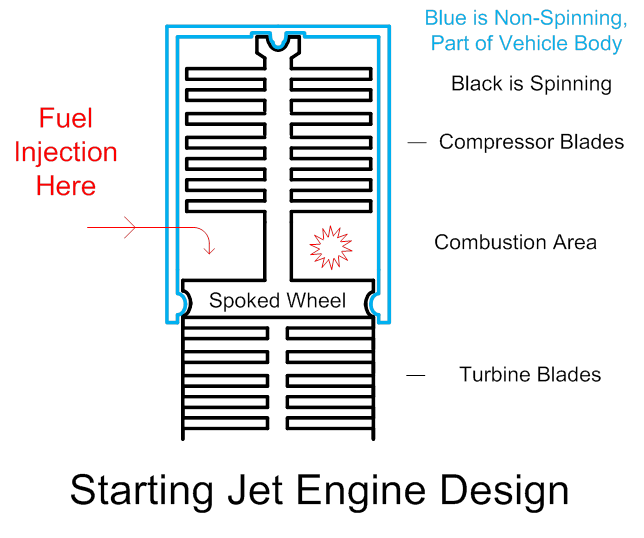
Figure
33 (above)
The
drawing is repeated with cross-sections side-by-side with the side view, for
further clarification.
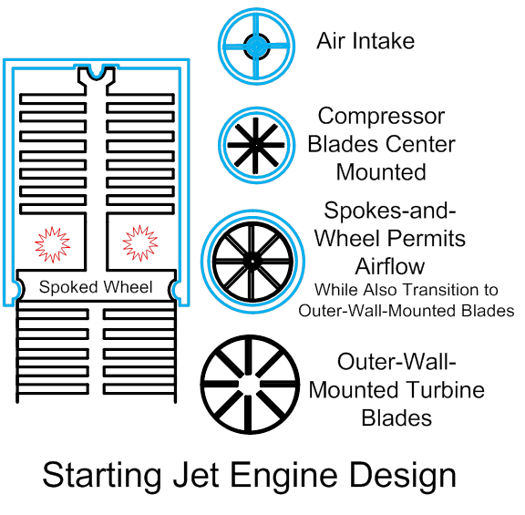
Figure
34 (above)
Note
that the spokes of the wheel could be tilted, in the same way as the turbine blades
are tilted, so that the spokes of the wheel, too, just like the turbine blades
themselves, actually serve as turbine blades as well as structural elements
holding the entire spinning assembly together.
Such wheel-spokes could also be several layers deep.
Note
also (as previously mentioned) that center-mounted blades are put into
structural tension mode, generally speaking, while outer-wall-mounted blades
are generally put into structural compression mode, by centrifugal forces. The turbine blades in the above design, then,
could be ceramic. Or they could be
ceramic-clad metal. The spinning outer
wall of the turbine area could be exposed to ambient air for cooling (or it could
be enclosed, either way). If the
spinning outer wall in the turbine area is left exposed to ambient air, it
could also have protruding propeller blades out into the ambient air, so as to
achieve 2 objectives simultaneously: Gather more cooling power, and propel the
vehicle forwards or upwards (create a turbo-prop, essentially). Also note that (since the blades are arranged
3-dimensionally), there is no reason why the center-line of the turbine area
must be left clear (the tips of turbine blades can over-lap). Also note that the turbine blades are NOT
restricted to being long-thin-knife shaped.
In order to resist any bending motions (which are not good for
ceramics), they could be shaped like a wedge or a shark’s tooth
(pie-slice-shaped). And then finally,
also note that the turbine area could be cone-shaped or rocket-nozzle-shaped,
so that (certainly at least at higher elevations, in thinner air) it could,
rocket-like, derive thrust from gas pressure differentials… ESPECIALLY if, later on during the ascent of
a rocket / jet hybrid’s ascent, the turbine blades were melted, cut, or blasted
away.
Alternately
put, how does a rocket nozzle derive thrust from a gas pressure differential
across the nozzle wall? Because the
higher (superheated) gas pressure below the nozzle wall is higher than above
the nozzle wall, as the rocket ascends, and the gasses-pushing-upwards-force is
NOT counter-balanced anywhere else on the rocket’s body. If, though, one has put turbine blades into
the nozzle, there is a down-wards thrusting (pushing) gas pressure differential
there from the top side of the turbine blade with respect to the bottom side of
the turbine blade, which is essentially pushing the vehicle back downwards
(this is just another version of the “no free lunch” principle; the derived
engine-spinning force of the turbine blades has a cost). Turbine blades are more harmful than helpful,
as the vehicle ascends, and the air is too thin to sustain jet-engine
mode. To convert to rocket-engine mode,
design your turbine engine blades to melt over time, or blow them out by
injecting explosives into the engine…
Or, if the enclosed-turbine-area design is chosen, there is even the
option of blowing out the entire turbine section!
In the
interests of making at least some of this more clear,
it’s time for some more drawings before moving on…
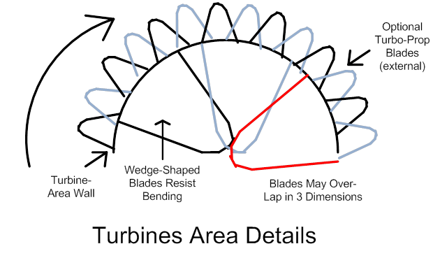
Figure
35 (above)
Now in
the below drawing, we are starting to migrate towards the variable-geometry
engine. Note that on the right side, we
can entertain visions of the launch-assist scheme. An upwards-pointed funnel
shape or shapes (with embedded one-way flow valve(s)) could receive propellants from the
assist scheme. Male on
the assist-side or propellant-injecting side, and female on the receiving side,
for easy de-mate at separation time, of course. Also the assist scheme could have other
provisions (motors, clutches, gears engaging to a small section of the outer
rim of the turbine area of the rocket’s engine) for helping to spin up the
rocket’s engines, right before lift-off.
Assist-scheme details have already been covered, and would not differ
much here.
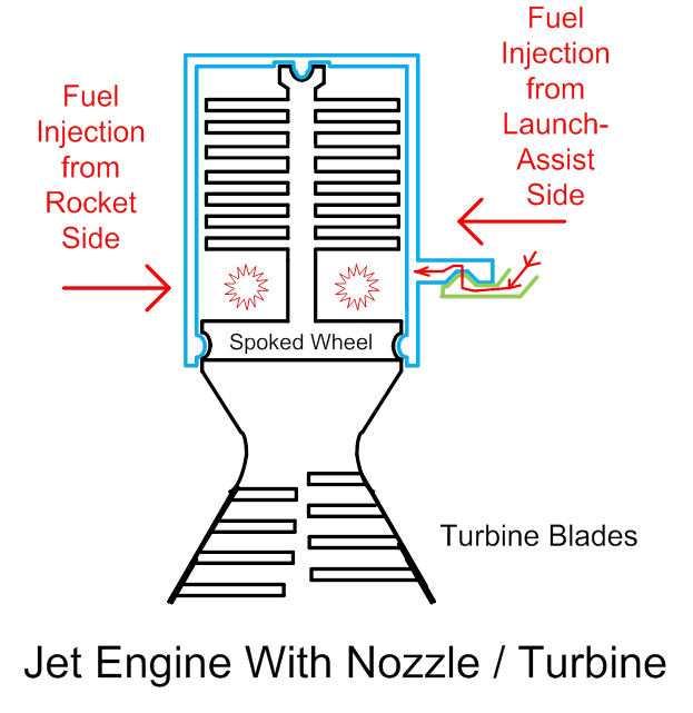
Figure
36 (above)
Now
what about more options for variable geometry?
If we cannot design a good scheme for “planned failure” of the turbine
blades at high altitudes (they melt out or we somehow blow them away with
explosives or abrasives or chemicals), then we might either have to live with
their parasitical effects at high altitudes, or we might enclose the entire
nozzle / turbine area and cut it away at high altitudes (yes, do that over the
open ocean, and warn ships in the region to clear out of the area, by all
means). Maybe a saw blade would do the
trick… Or cutting
torches, perhaps. Or a set of
strategically located explosive bolts?
If so, how do you keep engine heat from setting off the explosives
prematurely? Consult Wile E. Coyote!
Actually,
being able to cut out the turbines section is not all that crazy of an
idea… If the enclosing nozzle walls are
made strongly enough to resist a slightly chaotic separation of the turbines
section, and the (??) saw blades or cutting torches are applied at multiple
points around the spinning turbines assembly, it is not all that unreasonable
to believe that the separation could be accomplished without serious damage to
the enclosing nozzle walls. Also, if the
cutting away of the turbines was done progressively, proceeding from one thin
slice to another (instead of “one fell swoop”), that might help. Cutting torches, PLUS saw blades embedded
into the enclosing nozzle walls, might be a method by which all this could be
done in small bits and pieces, avoiding any large, uncontrolled, chaotic (i.e.,
destructive) events.
And
what about the compressor area? After the air is too thin to sustain
air-breathing jet-engine mode, then reactants added to your
now-a-rocket-engine-not-a-jet-engine, will want to blow hot gasses upwards as
well as downwards, which is not good at all.
That is, self-carried oxygen is going to have to start being injected
into the combustion chamber as the air gets too thin. AND, frankly speaking, if we are to have a
vigorous assisted-launch mode, with a large amount of reactants added during
that phase as well, then the pressures in the combustion area may be tempted to
“blow-back” upwards as well, during that time.
So it would be good to have a shut-off provision between the compressor
and the reaction chamber. Then if we do
that, we might as well also (during spin-up, assisted launch time, and also at
post-conversion-to-rocket time, ***IF*** we plan to just flat-out have to deal
with the parasitical effects of the spinning turbine blades) make provisions to
side-vent, downwards, the bled-off pressurized air from the compressors. If we are to bleed off (waste) compressed air
for any significant period of time, we will want to direct the air downwards,
for additional thrust. So add
(switchable) bleed-off-downwards-side-vents to the compressor, a shut-off gate
before the reaction chamber, and a provision for shedding the turbines
section. Some of these elements may or
may not actually make sense (some may be needed, some not). But here they are all, diagrammed.
Also
keep in mind, all of the air-breathing elements here can be supplemented with
regular rocket engines (for example, at the bottom of the rocket, while the
variable-geometry engines hug the bottom, outer periphery). The variable geometry engines need not
deliver greater than 1 for a thrust-to-weight ratio, ALL of the time, merely
MOST of the time. For example, a few
seconds or even whole minutes’ worth of slight ineffectiveness, immediately
after departing the launch-assist tower tops (if such towers are used), can be “paid back for” later on,
at higher speeds. Just at the end of the
day, we need to be better off breathing external air at least some of the time,
than we are, carrying all of our own oxygen, for the entire launch scheme.
PS,
the above drawing shows the turbine blades at a straight angle, which is not
good if we want more-pure structural compression mode for ceramic or
ceramic-containing blades. That is, if
we are to be honest, and include the downwards-pushing forces of the escaping
hot gasses on the turbine blades, as well as centrifugal forces, then these
blades must actually be tilted at least slightly UPWARDS .
This fault is corrected in the below drawing.
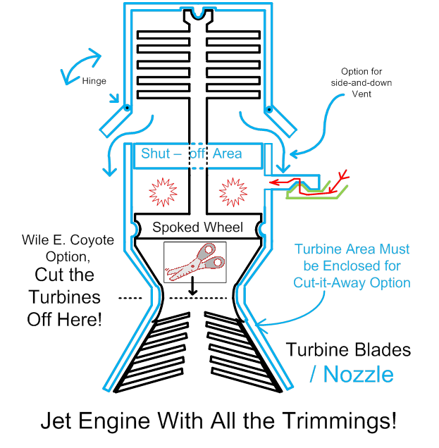
Figure
37 (above)
Actually,
the correction that has been made (in the angle of the turbine blades as we
moved from Figure 36 to Figure 37 above) is in the correct direction, if we
have ceramic or ceramic-containing turbine blades that we wish to keep in
“structural compression mode”. However,
the change may or may not have not gone far
enough… Where are all of you
public-domain rocket scientists that I have been looking for, to fill in all of
the details? Help-help-help!!! PLEASE help fend off the “patent trolls” and
allow humanity to escape to the stars!!!
What
might the shut-off area look like? This
is a mechanical detail. Basically we
could have fewer, taller-vertically, swiveling vent blades, or more,
shorter-vertically, swiveling vent blades.
Shorter means more complexity, but less space taken up. Taller means less complexity, but more space
is taken up. Vent blades must swivel
around motor-actuated rods coming in, presumably from the rocket-body side,
into the compressed-air section of the engine.
A round void in these vent blades must be left in the middle, for the
spinning shaft.
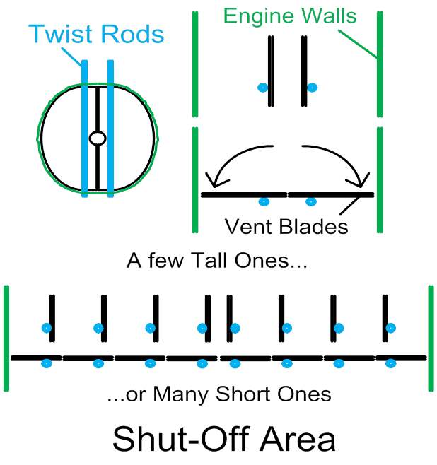
Figure
38 (above)
In
more detail, just exactly what would a ceramic turbine blade look like? In other words, the previously described idea
of cutting away parts of an entire turbine section, in flight, thus leaving an
enclosing nozzle behind, is plausible but probably not practical (or at least,
it is sub-optimal). It requires extra
mass and complexity, including the enclosing nozzle walls to be left behind,
AND it includes possibly chaotic and destructive materials behavior as the
cutting is done... And finally, it sheds
a lot of material that can do damage on the ground (or on ships at sea) far
below it. If we can design a ceramic or
ceramic-containing turbine blade instead, that melts, falls out, and/or fails
or otherwise fades away after the appropriate amount of time, then those blades
can go away and leave behind them, a rocket engine, without any of those extra
troubles.
This
is not at all as hard to do as one might at first imagine. There are some special devices that have been
used for centuries now, known as pyrometric cones. These are made out of ceramics
themselves. “Heat work” (heat soaked in
by the cone over time) slowly melts (turns internal particles into glass or
glass-like, thick-liquids) the cone.
These cones are used to mechanically trigger the turning-off action of a
ceramic kiln’s electric power switch, for instance (this author owns such a
kiln with cone-triggered switch). Here’s
the critical item: These cones are
precisely manufactured to melt (“fail”) at fairly precisely, the exactly amount
of “heat work”, or time and temperature, that is needed for a given kind of
ceramic, pottery, or porcelain firing (different cones are used for different
types of firings). So to imagine the
manufacture of ceramic jet engine turbine blades, that melt away, at the right
time (elevation), inside the variable geometry engine, is not at all very
far-fetched.
For
reference, see http://www.bigceramicstore.com/information/ConeChart.html and http://en.wikipedia.org/wiki/Ceramic (which says ceramics are already used as
coatings for turbine blades) and http://en.wikipedia.org/wiki/Pyrometric_cone (which describes cones as being made of
ceramics).
So imagine our
shark’s-tooth-shaped or pie-wedge-shaped, outer-wall-mounted turbine
blade. SOME parts of SOME of the turbine
blades, we will want to stay left behind, so as to form an internal
“constriction throat” for our now-a-rocket-engine. As the reader will recall, the constriction
throat is needed to make sure that the reactants stays there long enough to
create conditions of high pressure and temperature (and not be spewed out only
half-burned). One of the previous
drawings showed a hybrid jet/rocket engine with the spinning turbine section
having a constriction throat built right into the walls (figure 37). That may not be needed, and may cut into the
effectiveness of the design in jet-engine mode.
What if we built that tapered “nozzle wall” shape into the turbine blades
themselves? What if the turbine blades
closest to the combustion chamber were to have only their very tips melt away
over time, and then, the further that we travelled away from the combustion
chamber, more and more of the turbine blades was designed to melt and fall
away? The below drawing shows such a
turbine section… Melt-away-the-blades
areas in red, stay-behind-to-form-the-virtual-nozzle-walls parts of the turbine
blades in black. Why the thin
line of black into the red? Read further
below…
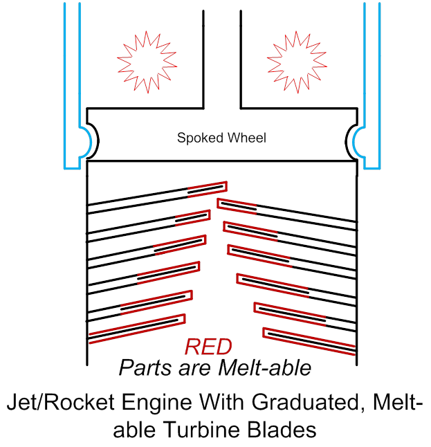
Figure
39 (above)
So
that’s what a cross-sectional view of a turbine might look like in this
scenario. As far as these turbine blades
themselves are concerned, their bases would be either solid metal, or solid
metal enclosed in protective sheaths of ceramics (if temperatures are so high
that the metal needs protection). If the
solid-metal bases do need a protective sheath of ceramic, then these pieces of
ceramic would be high-temperature ceramic, NOT melt-away-able, pyrometric type
materials. The melt-able tips of the
ceramic blades (the entirety of the blade as the aft-most or bottom section of
the turbine) would contain a metal interior for strength and resistance to
deformation, but… Here comes the
important part… They would be highly
perforated, Swiss-cheese style. These
perforations would be filled with hockey-puck shaped plugs of pyrometric
material, as would the entire section of ceramic material enclosing the
melt-able tip. All of this would be
assembled and glued together; the glue need NOT be temperature-resistant, since
centrifugal force in the turbine will push the entire blade assembly up against
the turbine wall anyways. After the meltable ceramics (pyrometric
material) melts away, the highly perforated interior metal core of the blade is
so perforated that it might as well not even be there, as far as the flow of
hot gasses is concerned. The remnants of
burned-away turbine blades will be slightly parasitic, yes, but not enough to
matter, if the design is done right.
The
metal core of the turbine blades, plus sleeves or sheaths of pyrometric
material (non-pyrometric ceramic, optionally, for the don’t-melt-it-away base
of the blade), and the hockey-puck pyrometric fillers for the holes, can all be
manufactured using today’s conventional methods, then glued together, using NO
complex or high-tech methods… Hand-into-mitten style.
This should all be relatively inexpensive.
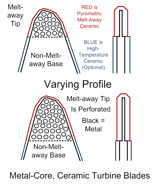
Figure 40 (above)
The
above-shown approach is likely the best, but this particular author must humbly
confess, that he is speculating, and doesn’t know the answers to many-many
associated questions, such as:
‘1) Just how bad really ARE the parasitical
effects of remnant, skeletal remains of turbine blades?
‘2) Are the metals used to make
high-performance turbine blades so horribly expensive (titanium for instance?),
that discarding some parts of some of them in-flight, would be unacceptable? Would this pose much of a safety hazard to
the earth below, to shed metal parts of blades?
‘3) Would the “virtual rocket nozzle” inside the
turbine area of figure 39 (where melt-away parts of blades taper off into
turbine blades segments that remain intact) be effective, or are there major
flaws in this idea?
‘4) Going way back to figures 36 & 37,
would the “constriction throat” (necked-off area in an hour-glass shape)
detract much from the jet-engine mode?
‘5) Does a rocket nozzle really HAVE to be
cone-shaped, or could it be barrel (cylinder) shaped, with good efficiency?
Depending on the answers to the above, alternate
scenarios for turbine blades composition and arrangements within the turbine
should be considered… And documented
here, once again, to fend off the patent trolls and the overly broad patents!
Consider, for example, a scenario in which case the
barrel-shaped rocket nozzle is judged to be efficient enough, and the metal in
the blades is considered inexpensive enough, to justify shedding them in-flight
(at high altitudes, where the air has become too thin, self-carried oxygen has
started being added to the reaction chamber, and the ceramic blades have
started to melt). In this case, the
ceramic blades could be made of many segments of metal core (no need for them
to be perforated in this case), enclosed, once again, in pyrometric
ceramics. The metal cores are segments
that couple to each other tongue-and-groove-style, but are encased in the ceramic. The tongue-and-groove mated metal resists
bending, even as the pyrometric ceramic turns weak, approaching liquid
state. After the ceramic melts away,
though, turbulent airflow, shock, and vibrations can practically guarantee that
the metal parts will decouple and fall away.
To guard against chaotic materials behavior ( all
of the blades falling apart at the same time due to a domino effect, possibly
endangering the whole vehicle), it would probably be best to use
low-melting-points ceramics at the innermost tips of the blades, and in aft sections
of the engine, working in a graduated fashion towards higher and higher melting
points as one works towards the outer walls of the turbine, and upwards or
forwards. Thus, the weakest parts will
fall out in a graduated fashion, without quite so much danger of “runaway
positive feedback” as engineers would call it (AKA “domino effect” in this
case). In this case, a cross-section of
a turbine blade might look like this:
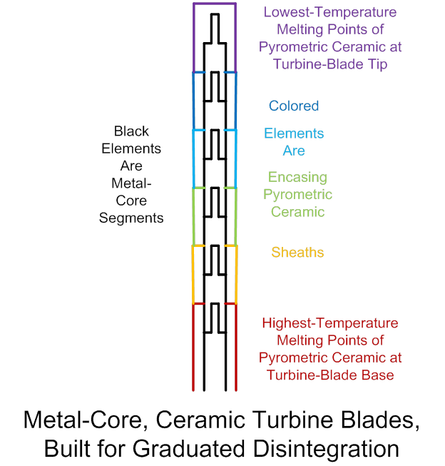
Figure
41 (above)
As a fine, miniscule little refinement of the above idea,
let it be mentioned in passing… A
fine-scale hooks-and-barbs surface finish on the tongue-and-groove mating of
the internal metal elements, could make it easy for the metal elements to
remain together, when encased by surrounding ceramic sheaths… Resisting shock-and-vibrations forces that
otherwise could loosen the cohesion of these internal elements. But those hooks-and-barbs fine-scale
elements, then, AFTER the enclosing ceramics melt away, will RESIST allowing
shock and vibration to put the metal segments back into their original mated
position! Resembling a one-way ratchet,
forcing the disintegration, but ONLY after the melting away of the enclosing
ceramic sheaths allows the freedom of motion for these internal metal elements
to overcome the “hooks and barbs” effect.
As
mentioned before, once again, all of this could be glued together with
low-temperature glue (admittedly
the complexity of manufacture has gone up, and the above scheme may become more
vulnerable to shock and vibration and the need for more secure fastening
methods may increase)… And centrifugal
force is our friend, if we stick to the whole scheme of mounting the blades on
a spinning outer wall, pointed inwards.
Centrifugal force will hold it together, till the ceramic elements melt
one by one, in a graduated fashion.
Absent an enclosing ceramic sheath, each metal element, in turn, will
shake loose and fall away. The
arrangement within the turbine area will facilitate gradual (non-traumatic)
disintegration of these blades, given that we already know how to finely
graduate the “heat work” or melting temperatures of required of pyrometric
ceramics, is “obvious to the casual observer”, as your engineering professor
used to say, and so will not be illustrated (for now, pending all of the fans
of this website banding together, and DEMANDING an illustration)!
So in the above scenario, this scheme would be suitable
for allowing almost ALL of the turbine blades to fall away… Leaving the question of, what serves to be
the constriction throat of the rocket engine, then? Perhaps one that is pre-built-in, as in
figures 36 & 37. But
if that is not practical… AND if
a properly shaped “rocket nozzle” in the form of a tapered cone is vitally
essential… If, otherwise stated, it is
essential that the escaping high-pressure gasses in the rocket nozzle have
“something to push against” as they escape out the aft end, at a correctly
placed angle, and loosely spaced remnant turbine blades just will not “cut the
mustard”… Once again, this author could
elaborate and add more drawings if needed to refine these points… Then just
perhaps it is time to consider a third and final configuration of turbine blade
construction, and arrangement of the blades within the turbine.
In the below, we theorize that a long “barrel shape” or
plain-cylinder shape of rocket nozzle will NOT suffice, and that the first
scenario (figures 39 & 40) is not efficient, either. The escaping hot, pressurized rocket-nozzle
gasses (molecules) just absolutely DEMAND that they have a nice, tapered
surface to bang off of, escaping out the back end, so as to make SURE that they
deliver optimum thrust to the rocket body (not sneaking off sideways and
muddying up our picture of thrust efficiency, as they escape, especially at the
very aft-most edges of the rocket nozzle or crude barrel pretending to be a
rocket nozzle, for example). Well, then,
what can we do to improve the escaping molecules’ chances of banging off at the
right angle? Especially knowing that
remnant turbine blades left behind, by their very nature, are loosely spaced,
providing a weak molecular rebounding surface?
Well, we are NOT out of tricks yet! The determined engineer INSISTS that dumb,
stupid, inert materials of the universe must obey our collective and creative
will! So what we do in this case is, we resort to an ages-old, common little trick that
everyone who has ever owned a door-hinge will recognize… We use a door hinge! 3 elements is all
that is needed… A
central bolt or rod to rotate around, and inter-locked fingers clasping the rod
from the other 2 elements of the hinge.
A simple hinge will be placed inside the metal core of the
ceramic-encased turbine blade. Hinges,
as we all know, can be built to allow motion in one direction, and in the other
direction, only up to a limit. The
turbine blade here envisioned has hinges built into the metal cores, that allow
the hinge (only after the encasing ceramics melt away) to bend the metal tip of
the blade, ONLY downwards / aft-wards, and NOT upwards. The encasing ceramic sheaths can be kept in
ALMOST pure compression mode, if we tilt the turbine blade VERY slightly
downwards, against the balance of the two forces… Escaping hot gasses push the turbine blades
downwards (aft-wards), and centrifugal forces push them upwards / towards the
turbine wall. The balance between these
2 forces is what was discussed earlier, and is why the adjustment was made
between figures 26 and 37, see above. So
now if we tilt the turbine blades very slightly back downwards yet against this
balance, in an engineering compromise, there will a tendency for the turbine
blade to “listen to” the pressures of the escaping hot gasses, which want to bend
the turbine blade the other way (downwards / aft-wards), and to discount /
ignore the centrifugal forces bending it towards the turbine wall
(upwards). The slight bias will keep the
partially-ceramic blade in MOSTLY compression mode, which is what we want
(ceramics are not good in tension or bending modes, our materials engineers
will always tell us). But now if we put
a one-way-limited hinge (with limited motion range) inside the partially-meltable metal-and-ceramic turbine blade, we can pretty
much guarantee, if a slight bias is added, that after the ceramics start to
melt away, the bend-able blade-tip will collapse downwards / aft-wards.
We want to avoid “domino effect” or trauma, and so we put
the lowest-temperature blade-bending effects aft-wards
(once again). We let the collapsing
(bending) blade-tips fall downwards (aft-wards), where they will rest on the
tips of their aft-wards neighbors (if they have any). Keeping in mind that this is actually very
three-dimensional, not two-dimensional as here shown in cut-away views, then
post-blades-collapse, a very-much-more solid (contiguous) rocket-nozzle wall,
in the more-conventional shape, will be left behind. ***IF*** it is highly desired for the sake of
efficiency, that the half-broken blades have tips that bend back towards the
turbine walls, then at least SOME of the escaping gasses will need a clear path
through the remaining stubs of still-unbroken turbine-blades-bases, from
reaction chamber to the aft edge of the turbine, to maintain spin energy (else
spin energy may be entirely lost, and hence centrifugal energy that keeps the
broken blade tips pushed outwards, will be lost also).
The below drawing follows the same conventions as
before… Rainbow colored, with RED colors melting at the
highest temperatures. This drawing
should suffice to illustrate the graduated bending-downwards of successive
layers of turbine blades, which will leave behind them, a fairly conventional
rocket-nozzle shape. Notice that a gas
channel is left, at the outermost edges, for conventional turbine operation to
impart at least SOME remaining spin energy, so as to maintain the outwards
orientation of the “broken”, hinged tips of the blades (due to centrifugal
force of course).
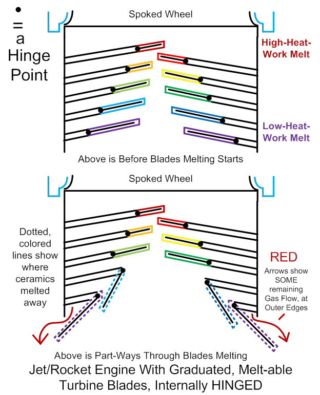
Figure
42 (above)
(OK,
the above drawing “cheats” a bit from top to bottom if one compares the two
drawings; the non-melt-away bases of the aft-most blades grew in length, but the
general idea should still be clear).
The
above-described turbines (partially ceramic blades, mounted on the outer wall
of a spinning turbine section of the engine) would work if the amount of “heat
work” required to melt the blades, is less than the heat energy spent during a
relatively short time that a vertically-launched rocket would need, to reach
the high altitudes where blade melt-down is a good thing. This idea is hardly implausible. ***IF*** the ceramics could be designed to
last even longer before melting, then an “aerospace plane” (conventional
horizontal, airport launch) could be based on similar ceramic-blade-based
designs. Keep in mind (refer back to
figure 35) that external turbo-prop propellers could be mounted, pointing
outwards, from the exposed outer wall of the spinning turbine area, for such a
design to be able to gain additional thrust (this would be especially handy for
an “aerospace plane” at low altitudes, it seems, to
this author at least). Also keep in
mind, such a heavy-lift aerospace plane could use mid-air refueling at about
40,000 feet or so, before proceeding further upwards. Mid-air refueling on the way up would be a
good way to economically boost large payloads up towards eventual orbit, in
this scheme… ***IF*** ceramic blade
melting can be postponed long enough, or if some other alternate solution can
be found, then melt-away ceramic blades may be part of the solution, for an
“aerospace plane”. Alternate examples: multiple engines, some not activated until
high altitudes are reached, or one vehicle carried or towed by another.
Variable-Geometry
Jet/Rocket Engines, Further Notes, Updated 9-9-‘12
Hi all you propulsion fans, I’m back
after a month-plus of not working on this web site. Please accept my apologies for an abrupt
change in writing style, but I’m tired of trying to keep this all rather
“professional” and third-person type style.
I’ve not been getting a ton of feedback from the “professionals” anyway,
so from here on in, I’ll be writing even less formally… More like me! But the subject matter stays all the
same… And the objective remains the
same! Fight off the ossification caused
by patent lawyers! Defensively publish
some more! I was sickened to see Apple
getting away with patents on “a rectangular-shaped computer tablet with rounded
corners”, and the like. So now can I
“defensively publish” descriptions of every conceivable size, color, and shape
of rocket and jet vehicle, and free the propulsion designers from future patent
slavery? Maybe! But that would be rather boring… I will try to stick with describing
seriously, significant ideas that might actually work. On the other hand, since I am NOT formally
educated or trained in propulsion, I don’t know very certainly at all, which of
my ideas are totally worthless, and which have good potential for working out
well. So, same as I have in the past,
when I come up with what I think are newer and better ideas, the older ones
(which I suspect are sometimes not as good, perhaps even worthless) will remain
documented here. I don’t know which will
work, and which will not… So they must
all stay, to carry maximum potential of fending off the patent lawyers. I want to take my vacation in orbit or on the
moon one of these days, and the patent lawyers are NOT going to help me get
there affordably! So back to the task at
hand!
Concerning the use of pyrometric ceramic materials in turbine blades, upon
further consideration, I now have hopefully better-optimized ideas here. The above are NOT optimized; the below are
better. Here is a summary, and then
we’ll get to the drawings for clarification:
The idea of tiling the turbine blades slightly upwards or forwards, into
the prevailing wind of the hot gasses if you will, is NOT the best idea, since,
in three dimensions, it complicates the arrangements of these blades, and it
isn’t really needed. The idea of
staggering the amount of heat-work required to melt the pyrometric
ceramic, so that the rear-most blades bend down first,
is retained as a good idea. The hinge
mechanism is selected as best suited for further refinement. The idea of coating or encapsulating the
entire turbine blade from hinge up to tip, is
discarded as un-necessarily expensive and massive (adds angular momentum as
well as mass). If, instead, the entire
turbine blade (including the hinge) is made of metal, and only the hinge is
selectively encased in pyrometric ceramics, then
these ceramics can be supported (and kept in compression mode) by adding a
protruding “ledge” of metal, right underneath the hinge. Hence, there will be no more need to tilt the
entire turbine blade upwards, and over-all mass is reduced.
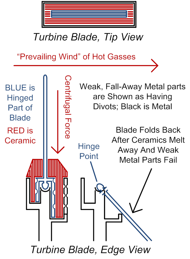
Figure
43 (above)
In the above drawing, as before,
centrifugal force keeps the ceramic materials in compression, so long as the
blades are mounted on the (spinning) outer wall. Note also that, if at the leading and lagging
edges of the blade, the ledge of supporting metal (on the non-hinged part of
the blade) extends all around the hinged blade (on both ends as well as both
sides), then the ceramics could be cast as one solid piece, covering the blade
like a glove covers a hand. This time,
though, the tip of the finger in the glove is cast aside, and, good
riddance! There is, once again, no need
to blend metals and ceramics together in any fancy manufacturing
processes. The ceramics could be glued
on, even using low-temperature glue, and centrifugal force will keep them in
place (for the short duration of a one-time flight life of the refurbished
blade). Using light-gauge wire,
bailing-wire style, to secure them as an additional measure, would be a good
idea, probably. This could be done by threading the wire through holes in the
blade, above and below the hinge and ceramics, to lightly encase the ceramics
and hinge area. Also, small holes in the
“base pan” or ledge of metal that protrudes from the blade, to support the
ceramics, might best be added so as to allow liquefied ceramics to flow out
(after pre-planned ceramics failure).
As far as the weak metal parts of the
blade (in both the hinged and un-hinged parts of the blade) are concerned,
these are there to mechanically secure and support the ceramics, and to provide
over-all mechanical security of the blade, but only up until such time as the
ceramics melt. Pre-planned weakness of
these metal parts could be achieved by adding divots, holes, or slots to the
metal, or simply by making these metal parts significantly thinner than the
other parts of the blade. The big
picture here is that it should be fairly easy to design a blade (as shown here
or very similarly) in such a manner that weak metal parts plus intact ceramics
makes a good strong blade, but the blade will fold when the ceramics melt and
the weak metal parts are then (by their lonesome, without the help of the
now-gone ceramics) no longer strong enough to withstand the “prevailing wind”.
The next drawing is simply a flattened
view from inside the turbine area, to show the obvious, which is that the
ceramic blades have to be tilted in order to do their jobs. Here they are shown both before they start to
fold, and after they start to fold.
Folding starts at the aft-most blades and works forwards, of course, as
controlled by different grades of pyrometric
ceramics. If you think about this in
three dimensions, you can see why I am discarding or disfavoring my earlier
ideas of tilting the blades into the “prevailing wind”; this change is a very
good way to simplify things.
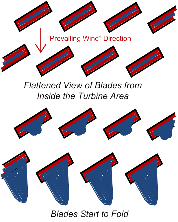
Figure
44 (above)
The next drawing shows a side view,
again, of the entire turbine area. If
you refer back to Figure 28, you can see a drawing of a “shut-off area”, which
for sure, would be needed in this or any other similar
jet-engine-to-rocket-engine conversion scenario, between the combustion area
(reaction chamber) and the compressor area, to prevent forward exhaust after the
air gets too thin (compressor fails). A
similar shut-off area (but with a much bigger hole or void in the middle) might
possibly also be needed to create a “constriction throat” as in a conventional
rocket engine. In the jet-engine mode,
the presence of the turbine blades provides an impediment to hot gasses
escaping, so as to improve the “dwell time” in a high-heat, high-pressure
reaction area, for combustion to complete.
In the absence of effective turbine blades after planned turbine-blade
failure, the constriction throat (partial shut-off area) may be needed. This of course would be located between the
combustion chamber and the former turbine area, now becoming a rocket nozzle.
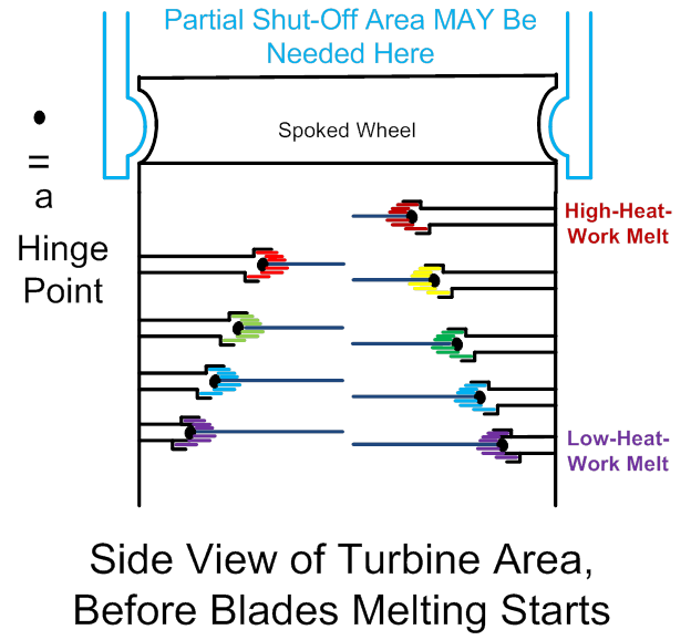
Figure
45 (above)
In
Figure #42 and associated verbiage, I previous stated that it is probably a
good idea to retain SOME spin to the turbine area (imparted by allowing for
SOME hot gasses to escape at the outer rim of the outer spinning wall of the
turbine). The spin is for the purpose of
retaining some centrifugal force, to force the tips of the bent blades out
towards the wall; to make the bent blades create a virtual (or partial semblance
of a) more-conventional rocket nozzle.
The escape of hot gasses at the rim, there, is going to happen, in this
design, whether we deliberately and intentionally design for it, or not, I
think, on considering it some more.
There really is little if any need to make allowances for it, either. The reasons why? Well, the “gas pressure differentials” across
a nozzle wall, that I mentioned much, much earlier, isn’t much of a relevant
way to think about things, in this case.
If you insist in talking gas pressure differentials here, well, then,
think about very, very little air pressure remaining in the high atmosphere,
and that , after the conversion from jet to rocket
engine, there is going to be WAY high pressure in the combustion chamber,
pushing upwards against the shut-off area, with nothing but thin air pushing
against the front or leading edge of the entire assembly.
The better way (in this case at least) to
think about rocket nozzles is, they prevent the hot gasses from escaping at
sharp angles away from the rocket body.
If the hot gasses escape COMPLETELY STRAIGHT (completely opposite the
direction of travel of the rocket) from the rocket, thrust is optimized. If they escape at anything approaching a
right angle, for instance, away from the flight path of the rocket, then thrust
becomes inefficient. The below drawing
should clarify this.
Anyway,
the presence of the bent blades, as well as the turbine walls, all of which are
in-line with the desired gas flow, will be plenty enough to prevent wild-angled
escape of the hot gasses. One more
drawing them for clarification…
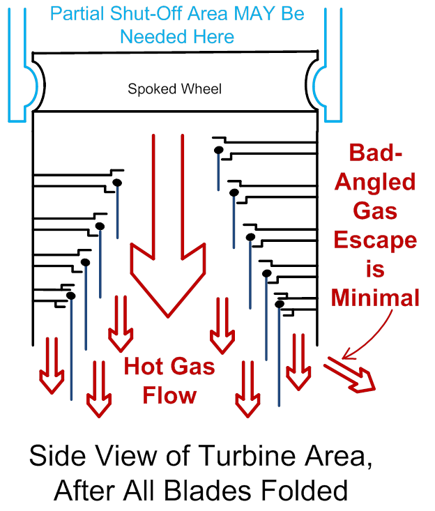
Figure
46 (above)
Note
that the shut-off area between the compressor and the combustion chamber can be
controlled in shades and degrees; it is not a binary on-off thing. The same will be true of the partial shut-off
between combustion chamber and turbine area (if this is used in the first
place). How does one determine, to what
degree is one or the other or both, to be shut off during what time in the
flight? Also, at what point in the
flight will self-carried oxygen start to be added to the jet engine, now
becoming a rocket engine? When does that
happen, and how fast? I will have to
leave this to the experts, to computer simulations, and to actual test
flights. I would suggest having strain
gauges in place in the mounting of each individual engine, so that performance
(more thrust means more strain, more metal being bent more) can be monitored,
per engine (not just measuring acceleration of the whole craft). Every few seconds, automated flight controls
could tweak these and other variables, to find the optimal settings, for each
engine. Turbine blade folding will
doubtlessly progress differently in each engine, and in each flight.
Variable-Geometry
Jet/Rocket Engines, Further Notes, Updated 11-10-‘12
One clear problem that
occurs to me, with respect to the entire scheme above, is, plainly and simply,
“wobbling”. As the blades fold, there
will inevitably be radial asymmetries built up in the radial distribution of
angular momentum. Think of the little
balancing metal tabs or weights that the car tire guy has to put on your
assembly of tire plus wheel, at the corner garage or tire-sales joint. Over time, the blades-folding process will,
despite our best engineering efforts, proceed haphazardly. So… One possible solution is to mount tracks all
around the outer circumference of the turbine area, which varying-sized weights
can travel around on. Wobbling would
tend to force these weights (if left to travel freely) to the outermost radius,
furthest away from the rotational axis…
Thereby worsening the problem! So
these weights would need to have a power source, and a method of propulsion (or
of crawling along the length of the circumferential tracks), and the local
intelligence (or signals from elsewhere on the vehicle) to direct them to
actively crawl AGAINST the direction in which centrifugal force “wants to” send
them.
I don’t have any
way-creative ideas on how to deal with all of that (hey all of you other
amateur would-be rocket scientists, where ARE you, PLEASE help out here!). Email me at RocketSlinger@SBCGlobal.net with
your ideas please; I will be happy to give you credit for your ideas if you’d
like that. The only possibly-helpful
suggestions would be, with any significant amount of air density left outside
of the vehicle (and that is the time during which the conversion process
happens, before we approach the vacuum of space), and no fixed outer wall
surrounding the spinning turbines area, then the balancing masses are free to
integrate into themselves, small fins or “sails” to tip this way or that way,
into the surrounding airstream, to gain propulsion or track-crawling
power. Perhaps it might be possible to
build into these crawling masses, sensors to detect which way they should
crawl. Here, I am short on details or
ideas. Vibrations (FREE energy in the
system!) might also somehow be of use. A
flip-able one-way ratcheting mechanism to NOT allow the weight to move in the
WRONG direction here, would fairly obviously be a
possibly helpful ingredient of the whole scheme.
Yet another approach would
be to have actively tilt-able external “turbo-prop” blades (see Figure 35)
pointing into the external airstream.
Dispense with the travelling weights on the circumferential tracks… Instead, tilt the external blades to throw
air outwards, away from the wobble (only on the correct side of the rotating
assembly) to push back against the wobble force, to correct it. Rather on the Rube-Goldbergish
side of things I would say… And of
doubtful effectiveness as air gets thinner and thinner.
A probably-more-implausible
method of active balancing might be to have mounted on the outside of this
spinning wall, a hollow tube full of dense liquid (water or oil). Build-in sensors all around the tube would
detect fluid pressure inside the tube.
Where-ever the fluid pressure is the greatest (where the off-center masses
have concentrated, and therefor started to make the engine assembly wobble), an
external energy source (??? Electric, airflow, vibrations,
???) would apply “squeeze power” or
displacement power to force the fluid to go elsewhere. Inflate small balloons inside the tube, say,
or have the tube itself be made of flexible, squeeze-able material (not
rigid). Force the mass of the fluid
inside the tube, then, to go to OPPOSITE of where it “wants to be” (due, of
course, once again, to wobble that starts to set in, sending the highest-mass
parts of the assembly out to an even greater radius, aggravating the wobble
even more… We need an ACTIVE, powered,
semi-intelligent entity here that wants to make our off-center masses “crawl
up-hill”, to go and kill the imbalance).
If the tube is rigid-walled, then some part of it
would need to be air-filled rather than incompressible-fluid-filled, so as to
allow the squeezed (displaced) fluid to be able to travel somewhere.
Another (simplest) approach
would be to give up on the idea of the spinning turbines area being
exposed. The idea in Figure 35
(pointing-outwards “turbo-prop” blades out there for additional propulsion at
lower elevations, in denser air) would then be excluded. But, by enclosing the entire spinning-turbine
area inside a fixed (non-spinning) outer wall, then another bearing surface can
countervail against destructive wobble forces.
This one deserves a drawing, see below.
Notice that the folding blades have deliberately been shown to have
folded asymmetrically (a prime, pro-wobble source of instability).
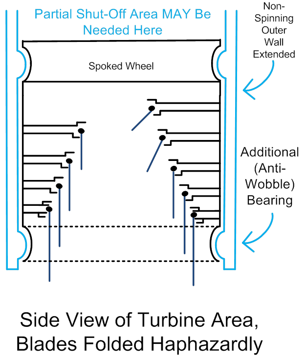
Figure 47 (above)
02-24-2013 Update: All
right, y’all have not listened to my desperate cries for help, here, in the
turbine-spin-mass, active-balancing-technology department, so, after many
months of background tasking this in my multi-processor brain, I have come up
with some better tentative solutions.
This particular root web-page is getting way too long, and so, I am
spinning off a sub-page at www.rocketslinger.com/turbine_spin_balancer/ …
Conclusions
Pre-stored
reaction mass (propellant), vertically arrayed, could be a practical (albeit
probably high-initial-capital-costs) method to reduce the costs of rocket
launches, at least as far vertically as tower construction economics will
permit. This is especially true if such
a scheme could enable the launch of rockets supplemented with air-breathing
engines (jet to rocket convertible, variable geometry engines). Jet propulsion could be a practical part of
the methods for achieving many elements of such a scheme. These (and related) ideas deserve to be
investigated and developed further. Jet
engines that can convert to rocket engines, especially those using
structural-compression-mode, pyrometric-ceramic-containing
turbine blades, also deserve to be investigated and developed.
Preview of Coming Attractions
Hi all
of you rocketslinger web-site fans! Unless I hear you want something else… Next thing I am working on, is to make the
below off-shoot web site (a sub-site), since this one is getting large enough to
load slowly, I suspect, for some folks.
Next I am planning to explore, suppose we use the
rail-embedded-with-reaction-mass (fuel, compressed air, water) idea as
presented here, but cut it down to ONE rail only, a large one. Suppose we mount it at a 30 or 40 degree
angle, maybe more, instead of vertically.
Now we can build it on a mountain-side.
Or we can build our own (perhaps skeletal, not solid) mountain to
support such a thing. How would we build
it economically? What sorts of things
could we launch off of it? Come soon to
a web site near you!
PS, Dear
Readers, I suppose I’ve ragged on the patent lawyers and patent trolls enough
by now… I’ll try to cut that out in my
new stuff. You’ve heard my views on this
already… And oh by the way, I don’t
resent patents that are narrowly targeted at EXACTLY what technology has been
developed, often at great expense. It
makes sense that such investments should be protected and rewarded. It is just that patents have become way, way
too broad, vague, and all-encompassing…
That’s what we’re fending off here.
Sub-Pages
(In
decreasing order of potential interest to the readers, as judged by Yours
Truly)
Recently
hybridized with new release-dates actually
Link,
sub-page, Sociobiology Tribalism Etc: http://www.rocketslinger.com/SocioBio1/
Link, sub-page,
Testing Quantized Inertia: http://www.rocketslinger.com/Quant_Inert2/
Link,
Moon Impact Cargo and Artemis Accords: http://www.rocketslinger.com/RIFFLE/
Link,
sub-page, Quantized Inertia Drives: http://www.rocketslinger.com/Quant_Inert/
Link
to sub-page, LionGlass ArtGlass etc.: http://www.rocketslinger.com/LionGlass/
Link
to sub-page, Aerostats and Zombies: http://www.rocketslinger.com/Aerostats/
Link
to sub-page, COPVs Part 2: http://www.rocketslinger.com/COPVs_2nd/
Link
to sub-page, COPVs and the Aston Omega 1 Engine: http://www.rocketslinger.com/COPVs/
Link
to sub-page, Hi-“G”-Forces Impact Cargo Addendum: http://www.rocketslinger.com/Hi_G_Cargo_B/
Link
to sub-page, Shuttlecock Lift Body Re-Entry: www.rocketslinger.com/Lift_Body/
Link
to sub-page, Shuttlecock Re-Entry Power Management: www.rocketslinger.com/Bifrost/
Link
to sub-page, A Badminton-Shuttlecock-Style Re-Entry Method: www.rocketslinger.com/BadMinton/
Link
to sub-page, Hi-“G”-Forces Impact Cargo Methods: http://www.rocketslinger.com/Hi_G_Cargo/
Link to sub-page, Ping-Pong Mass-Exchange Spacecraft
Propulsion: www.rocketslinger.com/Ping_Pong_ME/
Link to sub-page, Remote (Moon, Mars, etc.)
Recycling of Rocket Exhausts: www.rocketslinger.com/Xaust_Recyclr/
Link
to sub-page, Passively, Thermally Gated Flow Switches:
www.rocketslinger.com/Psv_Tgt_Fsw/
Link
to sub-page, Variable Configuration Rocket Nozzle: http://rocketslinger.com/Var_Cfg_Rck_Nzl/
Link
to sub-page, Mountain Mounted Rocket-Launching Rail: www.rocketslinger.com/MntnMntdRcktRail/
Link to
fictional works by Yours Truly: www.rocketslinger.com/RocketManFiction/
Link
to sub-page, Turbine Spin Balancer: www.rocketslinger.com/turbine_spin_balancer/
Link
to sub-page for Icy-Words Lander, AKA Europa Lander: www.rocketslinger.com/Icy_Lander/
Link
to sub-page about a totally different field of endeavor: www.rocketslinger.com/SemiLamarckism/
Anti-Patent-Trolls
Magic Spell at www.rocketslinger.com/Near_Universal_Defensive_Publication/
Link
to Texas Art Concrete, AKA TexArtCrete, a Sole
Proprietor Art Business:
www.rocketslinger.com/TexArtCrete/ (Web
Page not very active, business is idled)